
Bus Pirate is a great tool for exploring new chips using your PC , without the need to integrate the chip into a MCU project. Once I received my unit, i decided to put it to the test by exploring an accelerometer with I2C/SPI interface – the MMA7456L from Freescale. I am writing this in hope that it will help other people get started with BusPirate and I2C protocol in particular. I will only describe the I2C interface in this article but BusPirate is capable of so much more !
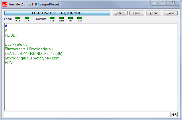
The setup of BusPirate was simple. Simply plug it to your USB port, install the FDTI driver (if necessary). After that it will appear as a virtual COM port on you computer. You then can use your terminal of choice to interact with it. Here is sample session in Termite (my choice of terminal software):
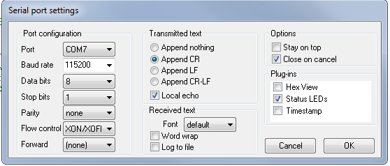
You will have to figure out which port your BusPirate is on. If you can't figure it out, unplug it , observe list of ports, then plug it back to see which new port appeared – that's the one. List of COM ports can be found in Device Manager on Windows or in Termite Settings menu. Other COM settings are as follows:
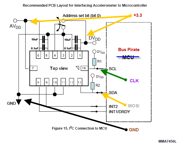
Using the probe cable accessory, I did all connections on a breadboard guided by the schematic from MMA7456L datasheet . You will need just 4 Bus Pirate probes connected to the accelerometer. Below I am showing which ones and where you should connect them:
On the breadboard this looks something like this (I also have the oscilloscope probes connected to CLK and MOSI):
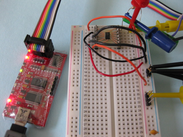
First thing to note – I used some shrink-wrap to isolate the Bus Pirate, but you can also put it in a case.
Second thing to note is that my accelerometer was mounted on a breakout board I made myself, I have a detailed tutorial how you can do SMT mounting and etch your own boards in my article "DIY Surface Mount on a Budget – Complete Walkthrough from PCB etching to Reflow" , check it out
Third thing – don't forget the the pull-up resistors (10K) on each bus line. It is required to pull-up the SDA and SCL lines (see resistors R1 and R2 on schematic). You can also try the BP pullup feature instead of external resistors. The BusPirate on-board 10K pull-up resistors can be connected to the bus pins, by connecting Vpu pin to a volate pin (3.3V), and then entering the p command to turn the pull-up feature on.
Finally, I used just one decoupling capacitor 0.1uF (the schematic shows 4 caps), also I did not bother to connect the N/C pins to ground.
However for stability you should ground the IADDR0 pin (3), on schematic they show a switch that allows a position where you can change the default address of the device. We won't need the switch for this experiment.
I later discovered that while using the BusPirate internal pull-up feature (Vpu connected to 3.3V), after I disconnect the oscilloscope probes the setup was no longer working!!! It must be the noise on the bus – I said to myself. Oscilloscope probes have 18-22pf capacitors that actually eliminate some noise. I encountered this phenomenon many times, so I knew what is going on. I simply added two 18pF capacitors between SDA/SCL pins and ground and I was back in business. The noise is coming most of all from my computer power supply , and while working at 100Khz it becomes an issue.
Ok, so once done with the hardware part, moving on to the BusPirate interface. First send a reset command and check your firmware/hardware version. A command is sent in bus pirate by typing the command # followed by Enter. Now take note of the version I am using , if you're reading this article in a year or two there might be other versions available, so if something doesn't make sense , it might be because your have a different version of BusPirate.
I2C>#
#
RESET
Bus Pirate v3
Firmware v4.1 Bootloader v4.1
DEVID:0x0447 REVID:0x3043 (B5)
http://dangerousprototypes.com
HiZ>
For a complete list of commands you can type ?, I won't cover all commands in this article I'll just explain the ones we use. By default BP is in HiZ mode. HiZ means "High Impedance". Z is a common symbol for impedance – simply a fancy way to say that all probes are disconnected. To enter I2C mode simply type m and choose the I2C option ( 4 – in my version of BP). You will be asked other details about I2C setup, I chose 100Khz speed. Once you enter a mode other than HiZ the green MODE led should turn on on your BusPirate.
HiZ>m
m
1. HiZ
2. 1-WIRE
3. UART
4. I2C
5. SPI
6. JTAG
7. RAW2WIRE
8. RAW3WIRE
9. PC KEYBOARD
10. LCD
(1) >4
4
Mode selected
Set speed:
1. ~50KHz
2. ~100KHz
3. ~400KHz
(1) >2
2
READY
Next step – you need to turn power supplies on – you do this by typing W (must be capital W !!! lower w turns them off). Once this is done, the VREG led will turn on, indicating you have power on your 3.3 and/or 5V pins. We'll just use the 3.3V pin to power our project and leave the 5V pin alone, however you could selectively turn the later off.
I2C>W
W
POWER SUPPLIES ON
Now it's time to interact with our accelerometer, BP has a set of macros for each mode that you can check with the (0) command, the (1) macro happens to be a macro that scans all I2C address on the bus and displays the ones present. Each I2C slave device will have a 7bit address ($1D for MMA7456L) that comes in two flavors read(R) and write (W). To obtain the 8bit read/write address you shift the 7bit address to the left (same as multiply by 2) and set the 0th bit to 0 for write, and to 1 for read.
I2C>(1)
(1)
Searching 7bit I2C address space.
Found devices at:
0x3A(0x1D W) 0x3B(0x1D R)
You can verify that 0x1D * 2 + 0 = 0x3A , 0x1D * 2 +1 = 0x3B.
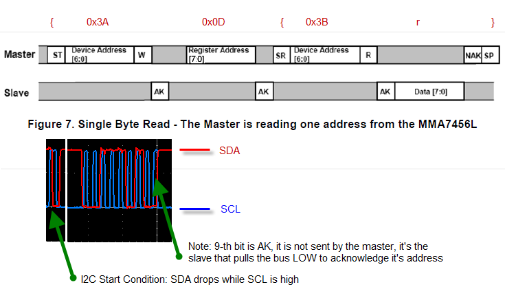
Now it's time to read something from the device. The MMA7456L configuration is divided into 1 byte registers that are described in the datasheet, for testing purposes let's read the register $0D that should contain the device I2C address (0x1D):
Let's send the following command and look at the output:
I2C>{0x3A 0x0D {0x3B r}
{0x3A 0x0D {0x3B r}
I2C START BIT
WRITE: 0x3A ACK
WRITE: 0x0D ACK
I2C START BIT
WRITE: 0x3B ACK
READ: 0x1D NACK
I2C STOP BIT
Now let me explain the BusPirate commands:
{ – sends a I2C start condition (ST)
} – send a I2C stop condition (SP)
0x3A 0x0D 0x3B are simply hex numbers representing bytes sent over the bus
r – reads one byte
There's no need to send the NAK signal, BusPirate will do it for you and also it will detect and display any AK(ACK) signals received from the slave (the accelerometer).
If this looks like magic to you right now , the following diagram will clarify things, it shows how I used the datasheet in order to construct a BusPirate command that would read one register. The register I am reading is $0D , which happens to be the device address, it should return $1D which is the I2C address for MMA7456L.
Now let's talk about writing a byte on the I2C bus.
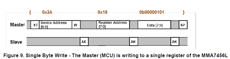
Before getting acceleration data , we need to put MMA7456L into measurement mode, we also need to specify the sensibility for which there are 3 options 2g/4g/8g. This configuration is done through the Mode Control Register $16 (get the details from MMA7456L datasheet , page 9). For our settings we need to send the binary value of : 0b00000101 which sets mode to "measurement", and g-select to 2g. Let's do it:
I2C>{0x3A 0x16 0b00000101}
{0x3A 0x16 0b00000101}
I2C START BIT
WRITE: 0x3A ACK
WRITE: 0x16 ACK
WRITE: 0x05 ACK
I2C STOP BIT
Writing a register is even simpler than reading and I will show you how the BusPirate write command relates to the diagram from the MMA7456L datasheet:
Now that we've mastered reading/writing to an I2C bus , we're ready to read acceleration data. We have the option of reading 8-bit signed values from registers $06,$07,$08. These registers have a 64count/g resolution in 2g mode, meaning that an acceleration of 1 g will be represented as 64 (0x40) and -1g will be represented as -64 (0xBF). We can read 3 consecutive registers from one command line as follows:
I2C>{0x3A 0x06 {0x3B r:3}
{0x3A 0x06 {0x3B r:3}
I2C START BIT
WRITE: 0x3A ACK
WRITE: 0x06 ACK
I2C START BIT
WRITE: 0x3B ACK
READ 0x03 BYTES:
0xFF ACK 0xF8 ACK 0x4A NACK
I2C STOP BIT
So we got following accelerometer output values for X,Y,Z axes: 0xFF (-1) , 0xF8 (-8) , 0x4A (74) which divided by sensitivity of 64counts per g, give us the values in Gs ~ -0.015g , -0.125g , 1.16g . It is close to what is expected from the output when the device is in horizontal position. The Z output seems to be off. We'll double check this and deal with it later.
Let's tilt the device on the X axis and see if it makes any difference in output, I tilted it roughly 45 degrees so that X and Z axis modulus should be roughly close to 64/2 = 32 and Y should remain close to 0.
I2C>{0x3A 0x06 {0x3B r:3}
{0x3A 0x06 {0x3B r:3}
I2C START BIT
WRITE: 0x3A ACK
WRITE: 0x06 ACK
I2C START BIT
WRITE: 0x3B ACK
READ 0x03 BYTES:
0xD7 ACK 0xF8 ACK 0x3F NACK
I2C STOP BIT
The results we got this time are X = 0xD7 (-41), Y = 0xF8 (-8), Z = 0x3F(63 !!!), now we can see clear that Z axis reading is offset. Luckily MMA7456L offers a way to correct these values and we'll use it. From first experiment we can see it needs to be offset by 74 – 64 ~ 10 counts. We can correct the accelerometer drift (for each axis). For Z axis we'll be using 2 registers:
"Offset drift Z value (LSB)" – register $14
"Offset drift Z value (MSB)" – register $15.
But what values should we write ? Let's start with the fact that our drift is about 10 counts, but this is in 2g scale. Scale in which drift must be specified is apparently 4g , so we need to offset Z by 10*4g/2g = 20 counts (in 4g scale) . Also our correction must be in different direction so the value to write is -20. Expressed as a signed DWORD this is 0xFFEC.
We'll write 2 registeres at once LSB (least significant byte) first.
I2C>{0x3A 0x14 0xEC 0xFF}
{0x3A 0x14 0xEC 0xFF}
I2C START BIT
WRITE: 0x3A ACK
WRITE: 0x14 ACK
WRITE: 0xEC ACK
WRITE: 0xFF ACK
I2C STOP BIT
Now let's check the readings in horizontal position again.
I2C>{0x3A 0x06 {0x3B r:3}
{0x3A 0x06 {0x3B r:3}
I2C START BIT
WRITE: 0x3A ACK
WRITE: 0x06 ACK
I2C START BIT
WRITE: 0x3B ACK
READ 0x03 BYTES:
0xFB ACK 0xF6 ACK 0x41 NACK
I2C STOP BIT
And here you go – the value for Z axis has been corrected to 0x41 (65) , close to what's expected ( 64).
In Conclusion:
This real life example of exploring and troubleshooting a chip with I2C interface shows what a valuable tool Bus Pirate is. Rather than bore you with a lot of theory and specs I tried to walk you through an example scenario I encountered myself. I hope that I interested you enough in Bus Pirate , accelerometers and digital interfaces in general to do your own further research of this topic.
//starlino//