
For anyone following this site, here is what I've been up to lately – building a quadcopter based on the Acc_Gyro 5DOF IMU sensor and a 16bit PIC. Although it's still a work in progress I decided to start putting together an article placeholder and build it up as project evolves. It's going to be a long one !
The source code will be Open-Source and will be hosted on Google Code, you can get code for quad copter here:
http://code.google.com/p/picquadcontroller/source/browse/#svn/trunk
As usual I like to start with a video demo, it's basically me controlling the tilt of the quad using a RC controller:
This is a PID feedback algorithm and a "Simplified Kalman Filter" as described in my other articles.
First of all there's a a RCGroups thread where I first introduced the project
http://www.rcgroups.com/forums/showthread.php?t=1235360
You'll find some specs there and I will put some material here as well.
Here is Revision 0.1 of schematic (what I started with):
The major parts list is as follows:
MCU: DSPIC33FJ128MC802 (http://www.microchip.com/wwwproducts/Devices.aspx?dDocName=en532302)
Sensors: 5DOF Acc_Gyro ( http://gadgetgangster.com/213 ) + 1Dof Pololu LIST300AL-BREAKOUT (http://www.pololu.com/catalog/product/765).
Motor Drivers: Power N-Channel Mosfets (Many choices -Low Rds(on) and rated for the current , I used IRLR8743 ). Schottky diodes to protect against back-EMF ( I used SS2H10-E3/52T )
Frame , motors propellers: I picked a ready platform that was on sale Dragandfly IV Frame these are actually brushed motors same ones as used in Esky helicopters.
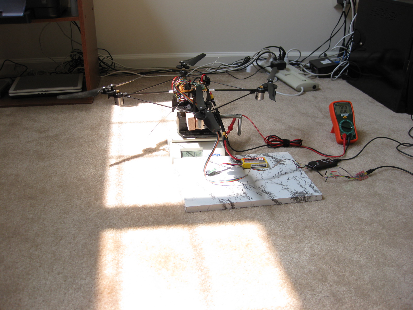
I did some tests on the lift force potential of this frame+motors+props, and was surprise to find out it performed better than some entry-level brushless motors. The lift force of this platform is up to 2.25 lbs. The results of lift-force experiments are compiled in this spreadheet: MotorLiftPower.pdf.
How I measured the lift force ? I didn't have any fancy equipment so I simply fixed the quad in a vise and weighted it it at different throttle levels – the difference in weight gave me the lift power.
For testing just one motor, I used a string attached to the weight:
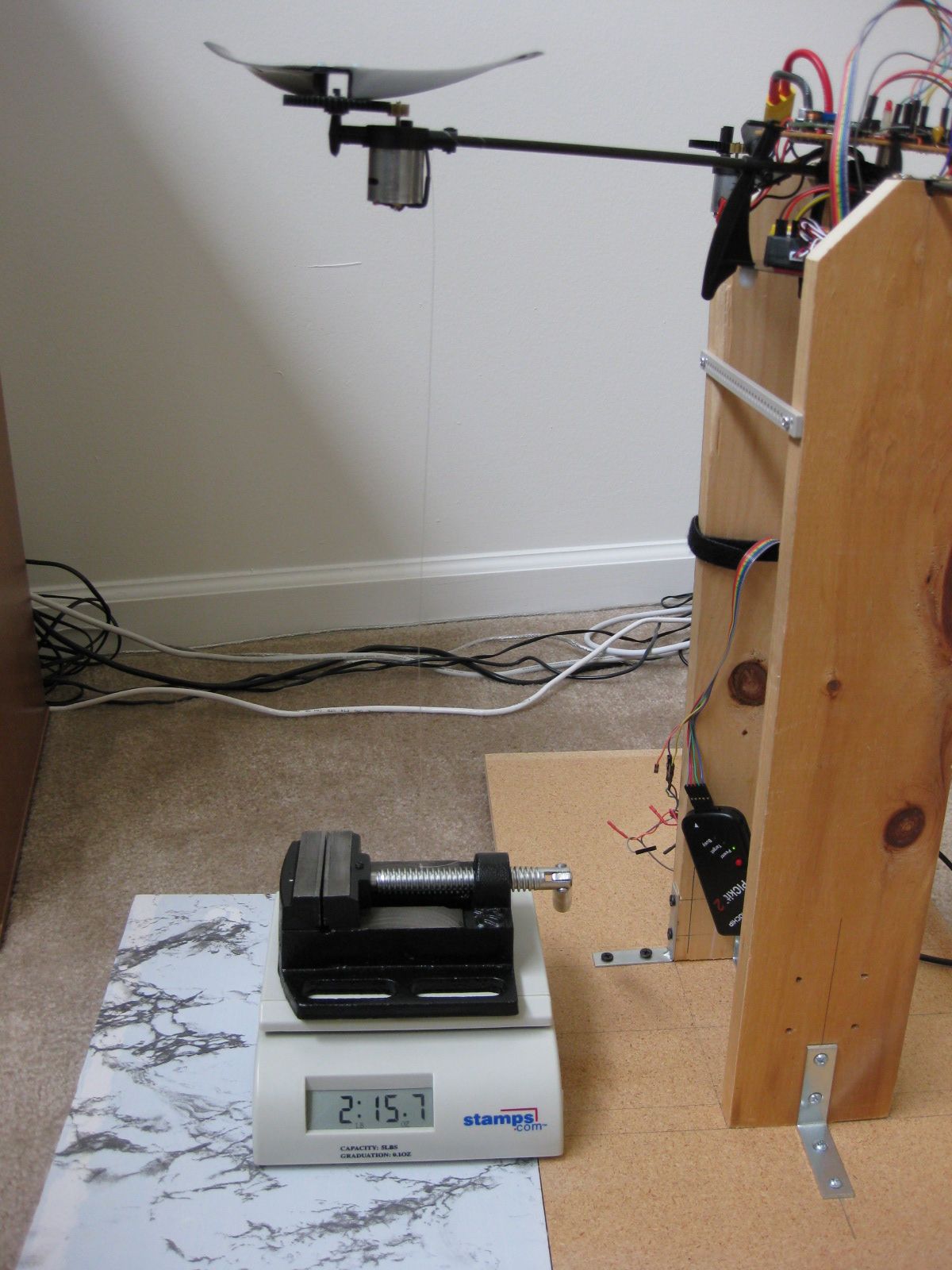
I built a test rig out of wood for testing the tilt balancing algorithm as you see in the video.
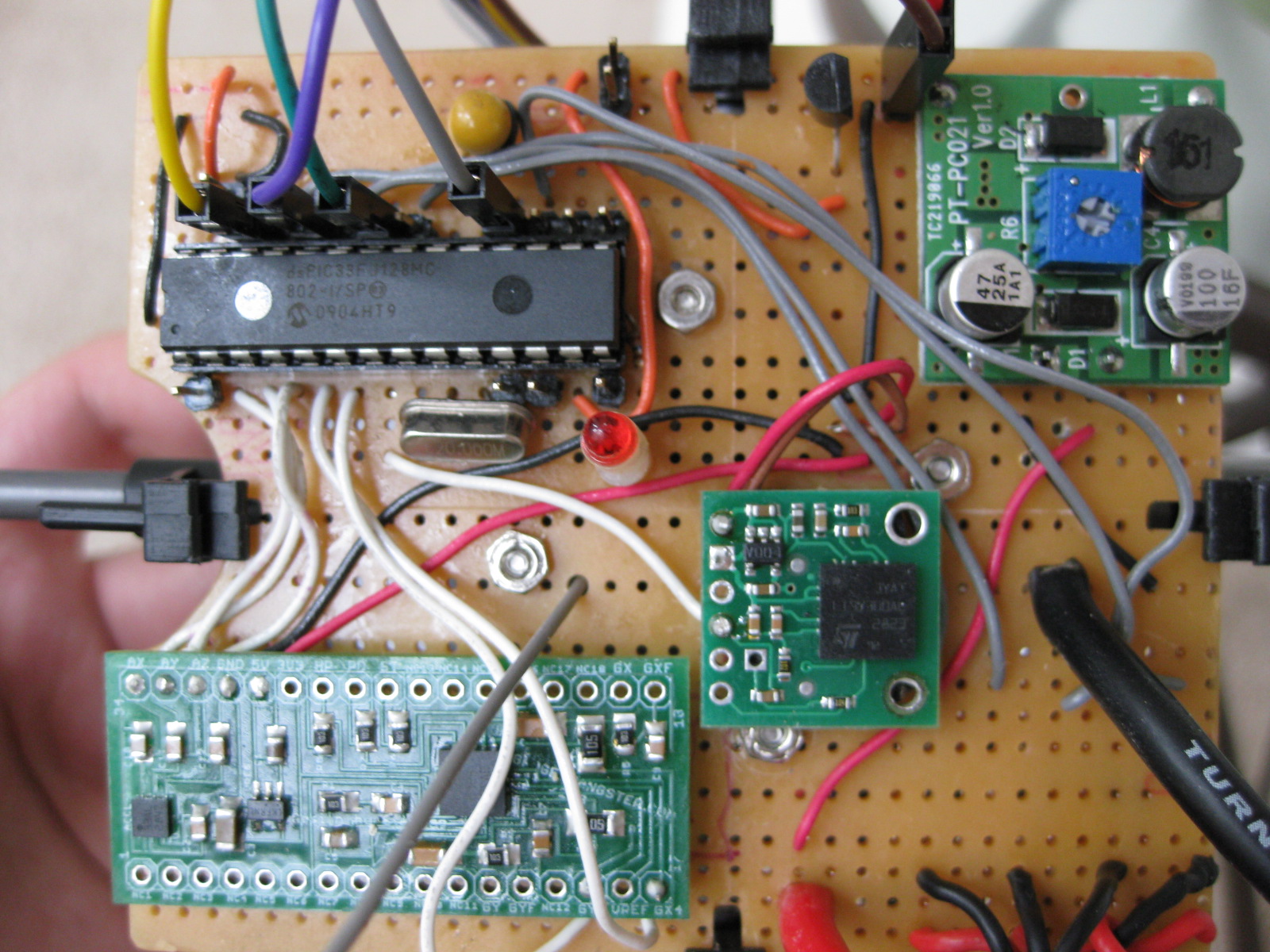
Here are some close-ups of the motor drivers. You'll see the Mosfets and the Schottky diodes, also note the extra solder added to support the high currents that will flow through those traces ( up to 5A per motor !).

Finally here is a view on the top of the board ( notice the PIC , the switching regulator , Acc_Gyro 5DOF IMU and single axes Gyro breakout , from top-left to bottom right).
This is it for now hope to bring you more interesting stuff on this and other projects if time allows !
//starlino//
good job!
what is really impressive is that you have manage to keep the code and the schematic quite simple, but the result is there!
Hi,
Can anyone help me please regarding integration of gyro and accelerometer? I have a 3 axis gyro and a 3 axis accelerometer. I tried to look at various sites but I am not managing to get an angle. Please help me
Regards
Jesmond
Nice work. Look forward to seeing it flying.
That base platform seems like a fast way to go, provided the brushed motors are sufficient.
Pingback: WWW.Analyst-TW.com » Pic based quad controller
I’m Doing the same thing but with a PIC18f445, I hope that it works soon, jejeje… I was looking up the Kalman filter when a saw your article, and I liked, I will use this in my project. Maybe, It will be a good Idea if you post your code… if it’s not a problem, thanks…
anfedres : the source code is here:
http://code.google.com/p/picquadcontroller/source/browse/#svn/trunk
Nice work starlino very usefull for my own quadrocopter project with a dsPIC33FJ128MC706.
Build my own BLDC controllers, and maincontrol board with ITG-3200 and BMA180.
But I have a question over your code. You have the variable throttle wat does is do ? Is purely to move the quad up and down or also voor turning an moving forward.
I can not make up from your code how you move your quad forward, backwards, left and right.
I want to start controlleling my quad via UART and just the gyro to test it. And than use your filter algorithm
Jeroen – current code is aimed at stabilizing the craft in the air so there is not forward/back/side motion. To see the code in the video , you’ll need to go couple of revisions back in the SVN source control tree. I’ll eventually get to implementing movement … when I get time.
Starlino,
Oke, that is my plan also first to stabilize the single axes X and Y. Question about the gyrocalibration. What do you do with, is it only for checking if the gyro is within the gyro adc span of do you use those values in de angle estimation.
My first test drive only with fixed motor speeds its very stable, sensors not used.
http://users.telenet.be/CyrusTheVirus/Quadrokopter%20Multimedia/MOV_0038.3gp
Starlino,
Oke that is what I thought. I also want to make it fly stabilized first. Also made a holder for the quadrocopter to test every single axes.
My first attempt, this is stable just on fixed motor speed no sensors used:
http://users.telenet.be/CyrusTheVirus/Quadrokopter%20Multimedia/MOV_0038.3gp
Alo you have al calibrate gyro function. What is de purpose of that function ? Is it just to validate that the gyro or are you also using the gyro max min and span for other purposes like for angle estimation ?
Jeroen really nice build the calibration is necessary for gyro because the voltage that corresponds to no movement is never according to specs, MEMS devices get offset during soldering, but that offset is usually constant over lifetime of device. Best way to handle that is to measure the zero voltage level experimentally during device startup when there’s no movement.
Yes, I found that out myself yesterday :P. My Gyro offset was different for all three channels so I took the average of 100 samples and set that as my offset. The extreme drift was almost gone.
I will built a gyro_offset routine in it so I can calibrate it once a while. The next step is getting the ACC to work and than put them together with your IMU code.
Have you every tried a complemantary filter ?
Jeroen, the algorithm described on this site – I like to call “Simplified Kalman” , but it is actually a complementary filter.
Ah indeed it looks alot like complementary filters i have seen elsewhere.
In the change log stands the following:
“Milestone: achieved short flight ,
stabilized Yaw, still not stable on
Roll/Pitch”
What do you mean by this that the algorithm is not 100% correct or there needs to be some tuning done ?
Also seen yesterday that I need to calibrate the gyro everytime at startup. The offsets where different every time. I now see that you do that also.
Jerome , “Milestone: achieved short flight , stabilized Yaw, still not stable on Roll/Pitch” – it means the quad is stable on yaw (does not rotate around it’s own axis), but is inclined towards some direction , i.e. it is not 100% flat, I plan to handle this using the trim controls on the transmitter rather than trying to calibrate the accelerometer to some “flat horizontal position” values, weight distribution on the quad might change due to a camera mounted , etc so I would rather have an external control over fixing/specifying the “flat” position of the quad that I can use on the field.
indeed, I also have some offset angle off 1,5 degrees.
My first filter test:
http://users.telenet.be/CyrusTheVirus/Gyro+Acc%202.jpg
I calculated the angle with the Unit vector R so the angle is Ayr. The gyro is integrated with gyroanlge=filterangle(n-1)+gyro*dt. With that I have no drift due zero rate offset. With gyroangle=gyroangle(n-1)+gyro*dt, I get angle drift due zero rate offset.
For gyroangle=gyroangle(n-1)+gyro*dt you’re simply integrating gyro values (and thus accumulating error) , and this is called integration drift. Have a look here:
http://www.programmershere.com/questions-answers/247601-combine-gyroscope-accelerometer-data.html
Filtering now also works in the uC. Only I can’t get the control loop stable it is or to slow or it is oscillating
http://www.youtube.com/watch?v=M06IJmbHbMk
What are you using for feedback control ? May I suggest P-D (you may later add I so it will be full PID control) : for P factor use the error (aberation from target inclination) for D factor you can use the gyro readings directly since it’s going to be equal to dError = Err1 – Errr0 = ( Pos1 – Target) – ( Pos0- Target) = Pos1 – Pos0 = dPos (gyro reading) . You will then need to adjust the Kp and Kd parameters in equation Control = Kp * Error – Kd * dError . Otherwise looks really cool what software are you using for charting ?
This is my code:
ITG3200(&Gyro.TEMP, &Gyro.X, &Gyro.Y, &Gyro.Z);
Gyro.X-=Gyro.Xoffset;
Gyro.Y-=Gyro.Yoffset;
Gyro.Z-=Gyro.Zoffset;
BMA180(&Acc.TEMP, &Acc.X, &Acc.Y, &Acc.Z);
AngleGX=AngleX+Gyro.X*0.005;
AngleAX=atan2(Acc.X, Acc.Z);
AngleAX*=57.29577951;
AngleAX+=OffsetX;
AngleX=(filtergain*AngleGX);
AngleX=AngleX+((1-filtergain)*AngleAX);
AngleGY=AngleY+Gyro.Y*0.005;
AngleAY=atan2(Acc.Y, Acc.Z);
AngleAY*=57.29577951;
AngleAY+=OffsetY;
AngleY=(filtergain*AngleGY);
AngleY=AngleY+((1-filtergain)*AngleAY);
DeltapitchX=AngleX*GainX;
DeltapitchY=AngleY*GainY;
Motor.F=17500-DeltapitchX; //FRONT
Motor.B=17500+DeltapitchX; //BACK
Motor.L=17500-DeltapitchY; //LEFT
Motor.R=17500+DeltapitchY; //RIGHT
pretty much the sames as your code. You also dont have real P or PD or PID control loop. Or is throttle just to turn the quad ? I have hadded 17500 (30000 is 100%PWM, 15000 is 50%PWM) as offset. the D parameter is normaly just to speed up the proces, but first it needs to be stable with the a P control.
I use Labview 2009 as my log software.
Here is another video
http://www.youtube.com/watch?v=9iuki1sWK8Q
(there is a bug also that sometimes the BLDC controller receive wrong setpoint).
Now implanted a PD controller which seems to work good:
http://www.youtube.com/watch?v=XTHs8anvv3s
But you didn’t use any D or I terms in your control just P control, am I right ?
I now made a PD control on the angluar velocity which seem te work with little drift:
http://www.youtube.com/watch?v=lfPuM1grSLQ
But the absolute angle control won’t be stable with PID controller. What could it be the angle calculation or something else (2 posts above). With a P-gain of 10 is starts oscillation and it isn’t still at all.
looks really good, I am now behind you on this project :) have you thought of recording the readings from sensors/control wirelessly and then mapping it on the video (you can use led to synchronize start of recording), that way it would be easier to debug those drifts. it’s hard to tell at this point what is wrong , can be more than one thing.
http://www.youtube.com/watch?v=KZQXdGFWGXE
In this movie you can see the drift
here is an excel sheet with step reponses of one axis with a sample time of 1ms.
http://users.telenet.be/CyrusTheVirus/response.xls
Ohh I think you should also consider introducing the I (integral of errors) , this looks like a prolonged drift that is exactly what I factor fixes. Find a good resource of PID tuning and try all Kp, Kd, Ki factors I think you’re close. With integral you have to make sure it doesn’t go crazy (so you have to limit how much it can grow, reset or trim it from time to time).
I have tried I term but it doens’t seem to help much (just a little bit). I made a better test stand so the quad can rotate on one axis at full speed (2000deg/sec) with this I can determine the step response and make a model for matlab. Which makes is easier to tune. I have done this yesterday but I only could measure 1sec which it not enough.
From the results of yesterday I have seen that there are high frequence noise when the quad is rotating. So I have to look to the optimal setting for the internal filters without to much phase delay.
Jeroen , how about a mechanical dampening of the sensors, after I mounted my sensors using foam tape instead of inserted in socket, I got much less noise.
I tried holding the sensor with my finger (still in pinheader socket) and see no difference.
Here is a video of the output of the gyro white line deg/sec:
http://www.youtube.com/watch?v=dzetSxw3S-Q
I just found out setting the bandwith in the gyro to a high level gives less drift 1kHz sampling 100Hz bw is worse than 8kHz 256Hz bw with much less phase delay. This is because of the higher bandwith I could set P-gain to 22 instead of 15 which seems to help. Still a bit jittery but this could go away with tunig.
To bad my battery is empty and only have one.
I now got the angle velocity control pretty stable
http://www.youtube.com/watch?v=h9_zp5WW4jo
This is ony 200Hz PID controlled loop (now able to run on 1kHz).
I can’t get the angle control stable, deleted my angle filter and implanted your seems to work good. But cant get the control loop stable. I logged some data form the motor control value and the angle when is osscillation and used matlab to determine a model but this fits reality. Did this also with angle velocity control loop that works perfect.
Do you no how what the frequency response of your filter looks like ?
Jeroen, it is so much better now , I didn’t do an in depth analysis of the frequency response , all I know it is an IIR (Infinite impulse response) low pass filter, the cutoff frequency is determined by wGyro , which I determined experimentally by collecting data with motors on. Please note there’s yet another filter in my code it’s a simple averaging filter in the adcutil.h module , it collects 16 samples to the DMA buffer and then averages them for the loop interval mine is around 6 ms since I use direct PWM to motors not servo controllers which requires at leas 10-15 ms to work properly.
that is what I thought, I tried several values ranging from 5 to 20. wGyro=20 gives a nice smooth signal but the quad starts osscillating at a lower gain. I think this caused by the phase delay of the filter. Also played with the internal filters in my gyro and acc. Set my gyro to 188Hz low pass filter which works fine in angle velocity control mode. So let the gyro the same. The Acc has also an internal filter ranging from 1200Hz to 10Hz cutoff freq setpoints. If I also lower this value to 40Hz it also starts oscillation faster.
I do see alot of noise on the angles when the motor is on. This can be reduced with the internal filters or wGyro but the quad will start oscillating. All ready posted on RCgroups but don’t get much response.
Tonight will also try to get the tranfer model of my motors so I can tune them better. Matlab is a great tool for tuning.
Jeroen , you should not disregard the fact that you can improve mechanical factor (make sure weight is balanced, introduce amortization under sensors foam/tape). For example my quad was drifting yesterday at one side I discovered it is not balanced I repositioned some components to make it more balanced and got better results. I updated the code :
http://code.google.com/p/picquadcontroller/updates/list
There is still a lot of tuning to do, flight is far from stable, but much better, and I am able to “trim” the roll/pitch/yaw command values, the params I use with best results are Kp(Roll&Pitch) = 25 , Kd(Roll&Pitch) = 200 , Kd(Yaw) = 80
I can see it starts oscillating if I increase Kp(Roll&Pitch) since this signal is delayed and not very reliable when quad is subject to external accelerations, I modified the imu.h code to observe if modulus of acceleration is far from 1g to give more weight to gyro and less weight to accerlerometer. I actually replaced wGyro with accWeight as you’ll see in the code but that’s equivalent.
I shall look on the new software, waiting on one new motor a bearing broke due a crash.
Updated my BLDC controller to run on 2kHz controlloop. The acrobat mode runs now on 1kHz not yet tested due the motor. Also orderded some rubber dampers to reduce the vibarations. hopefully I’m have some time to test more this week.
The adaptive wGyro could be a good thing. I will keep you updated
How big is your angle noise when quad is still and motor turn. I see about few degrees noise. This discreases when I ingrease wGyro. Also want to try put some white noise on the motors and see what the angle does to determine a model in matlab.
Also bolted the electronics on rubber, but don’t see a big difference in noise.
Hi~ guys, currently i headache with programming the pitch and roll axis of quadcopter.
Right now , i fixed the quadcopter on the wood structure for control the front motor and back motor speed , in order to achieve balancing flight.
I’m using Arduino as microcontroller, and 5 DOF IMU (gyro and accelerometer) to determine the estimated angle.
In my programming,i stated that ,if overall buttons are at the low condition, which means all buttons are switch off. Then i using P term for balance the QuadCopter, the programme as below:-
if(digitalRead(UP_button)==HIGH && ButtonRelease1 == true)
{
x=constrain (x+20,1000,1800);// front motor
z=constrain (z+20,1000,1800);// back motor
ButtonRelease1 = false;
}
if(digitalRead(UP_button)==LOW ) ButtonRelease1 = true;
if((digitalRead(UP)==LOW) &&(digitalRead(DOWN)==LOW) &&(digitalRead(FORWARD)==LOW) &&(digitalRead(BACKWARD)==LOW) &&(digitalRead(LEFT)==LOW) &&(digitalRead(RIGHT)==LOW))
{
int Kp; //tuning parameter,Kp
int Pout; // Proportional output,which is P term.
int Sp=0; // Setpoint
int PV ; // process value, angle estimated
Kp=1;
PV = ( Rate_of_Estimated_Angle * 90 );
Pout = ( Sp – PV ) * Kp ;
X=x-Pout; //x is previous front motor speed
//X is the new motor speed
Z=z+Pout; //z is previous back motor speed
//Z is the new motor speed
}
PWM2.writeMicroseconds(X);
PWM4.writeMicroseconds(Z);
But the problem is —– The QuadCopter always fluctuating !!!! Any mistake i did wrong with the code as above ? Thanks for all ur information~
I am following and using this project as a beginning to our own UAV quadcopter project. I am going to use ESCs instead of the FETs and SchKotty diodes. We are using a similar PIC. Most other sites are using the Arduino boards and we are designing our own.
2 Quesitons: What is the best battery to use and what would be the recommended ESC to use as well?
I am using Rhino 1350mAh 3S 11.1v 25C Lipoly Pack (or something close and similar). I got them from http://hobbyking.com which seems as a good site for all RC parts. If you’re there grab a small camera for your first flight :) . What type of ESC do you need brushless or brushed ? In any case you can ask the veterans on http://www.rcgroups.com I am sure they have plenty to advise. As far as my project I settled on the onboard MOSFET to save costs. Brushless motors will last longer but will not necessarily give you more precise control since you can only update them every 10-15 ms. There are newer I2C brushless ESC though that can be updated more often but they are expensive. Any approach you take will have it’s challenges. I think PIC is great since you get 80Mhz processing and many features that Arduino does not have (yet). I have to agree C18/C30 is harder to program than Arduino but once you get it you will love the extra features and control you get.
Thank you Starlino for your article
Very Helpful !!!
Im Building my first quad with
Usb Hid Joystick -> C# Xbee Pic182550
Imu = AdxL330 +Lpr450AL
All card home made
Thanks Starlino
I have the same quadrotor structure and I use pic18f6520 and a 6 dof IMU but it seems impossible to fly. you can see my previous video here:
http://www.youtube.com/watch?v=DIP34T5SFtw&feature=youtube_gdata_player
Although I have managed to get rid of the vibrations I still cannot make it fly. My guess is to change motors to brushless DC and use ESC for speed control. Also I think we should change the blades too.
can you give me the source code for PIC programs. I really need it, I decided to make quadcopter for my final project. I need it as soon as possible
Awesome quadcopter!!, but as anyone have a look at or tried the Arducopter quad which uses the ardupilot mega board? I am interested in getting one but not sure how well it performs?
http://unmannedtechshop.co.uk/Ardupilot-Mega-2560-kit
can anyone tell me how to use the angle calculated for calibration of motor’s speed
nice job!I want to build my quadcopter too,and I was learning how to do it,I will always pay attention to your build.
Hi Starlino,
nice job there.
so your algorithm in here (http://www.starlino.com/imu_guide.html) was not used in this quadcopter project?
An implementation of the DCM matrix algorithm and sensor fusion described in this tutorial can be found here:
http://code.google.com/p/picquadcontroller/source/browse/trunk/imu.h?r=8
Once you calculate DCM matrix it’s up to you if you want to convert it to quaternions, euler angles, or any other type of angles that you can input into a PID process controller. I do not work with Euler angles, they are problematic and ambiguous at some limits.
hello im first time to do that project like quadcopter.i want change my project like auto control (not using controller).only PIC can control that copter.can anyone show @ explain what should i do? and how to get code programming , schematic and list of component NEED HELP!! plezz
Hi starlino,
Im trying to make a quadcopter from scratch (at least the firmware part). But before trying to fly around with the quad, first I managed to stabilize it in only one axis (like you did in the video). The stability seems to be fine but I made two attempts to take off and miserably crashed my toy. Is there any ‘catch’ in the process? I know it may sound too vague, but I can provide more information if you ask! I made a video showing its performance in one axis (http://dl.dropbox.com/u/27291314/2013-02-28%20quadcopter-teste-eixo.mp4) Thanks in advance!
hi guys! I have a mpu6050(IMU 6DOF). I want to use for myquadcopter.I use PIC16F877 as process.I use CCS C as program language.But I dont know how to use this sensor.which pin connect to PIC16F877.is the INT pin used? can you tell me which pin connect to where? wait your answer!!
THANKS..
Hi starlino!
Finally, after 3 hour's of recoding your code I can compile it on my LPCXpresso. I just compile it, but it is not functionally. I have to comment many line's. Rigth now I just want to try make DCM to work, just this.
So, I need to know how adcutil.h works. I have digital acc and gyro so I have to rewrite that part of code.
I'm thinking on make a regular reading of my gyro and my acc to fill adcAvg[6] with data. Let's say every ms on an timer interrupt. How often your ADC make a convercion?
Well, I hope you can tell me something to start to work.
Best regards!
Leonardo – I am using an advanced PIC feature ADC with DMA ( so the readings are written to memory permanently in the background), then averaged. I think you will be fine with readings every 10ms or less. Look at your datasheet for the required aquisition time for your ADC, but I suppose 1ms should be enough for each channel.
Starlino, once again, thk for your answer. So I will read my sensors (by I2C) every 5 msec in the background.
Then in my main I will call imu_init, and on infinite loop I will call to imu_update to maintain DCM matrix… Well I probe that and I will report later….
Regards!
~~#include <p32xxxx.h>
#include "commontoall.h"
//400Hz control loop timer
void Setup_Timer1()
{
IEC0bits.T1IE = 0; //Disable timer1 interrupt
T1CONbits.TON = 0; //Disable timer
T1CONbits.TSIDL = 0; //Continue operation in idle mode
T1CONbits.TGATE = 0; //Timer gate accumulation disabled
T1CONbits.TCKPS = 0b01; //Timer prescale 1:1, 1:8, 1:64, 1:256
//T1CONbits.T32 = 0; //32 bit timer disabled
T1CONbits.TCS = 0; //Internal clock source
IPC1bits.T1IP = 0b100; //Priority 4
//Frequency of 400Hz
PR1 = 12379; //Period register
TMR1=0;
T1CONbits.TON = 1; //Enable timer
printf("\nTimer1 Setup Complete");
}
void __ISR( 4, ipl4) InterruptHandler (void)
{
IFS0bits.T1IF = 0; //Clear interrupt flag
IEC0bits.T1IE = 0; //Disable timer1 interrupt
LATAbits.LATA0 = !LATAbits.LATA0;
Get_Gyro_Rates();
Get_Accel_Values();
Get_Accel_Angles();
//complementary_filter();
second_order_complementary_filter();
//update_PID();
//update_motors_single_shot();
IEC0bits.T1IE = 1; //Enable timer1 interrupt
}
………………………………………………………………………………………………………………………………………………….
Please help me remove the error!
I am trying to run MPU6050 GY-521 breakout board on my UBW 32 bit wacker board of PIC32MX795F512L controller available at sparkfun.com
i have converted your exact code and have arrived at an error in>>>>>>>>>>>> timer1.c
the error occurs at the interrupt service routine start .
above is my code (infact your code converted from dspic33f to PIC32
commontoall.h is the same common.h file renamed
starlino please help me!!!!!!!!!
So what is exactly the error message ?
it it as follows>>>
Timer1.c:26: error: syntax error before numeric constant
it occurs at >>>>>>> void__ISR(4,ipl4)InterruptHandler(void)
void __attribute__ (( interrupt(ipl4),vector(4))) InterruptHandler( void)
ok thank you i have got it right myself by replacing the entire declaration as mentioned above
ok thank you i have got it right as follows>>>>>>>>>
void __attribute__ (( interrupt(ipl4),vector(4))) InterruptHandler( void)
starlino,
is it that your google code is really working ??
i,ve tried half of your code mostly comprising of gyro and i have set up the oscillator and the timer 1 according to my PIC32MX795F512l controller
u,ve also used the serial lines in your code starting with >>>printf<<<< so im trying but your code seems to have stopped working some where
and how are u seeing the serial data i can show you my entire project if you like by mailing you if you let me know your mailing id
starlino, how do you see your serial data?
in my code ive used timer2 as a delay timer to create delays and also ive used lcd.c file to put some characters on lcd using pmp module of the pic32
but your code seems to stop some where since it looks like that it is not reaching the lcd code that i have added
the lcd code has nothing to do with your code yet i was just testing it so that i could later use it to put my gyro and accelerometer values on lcd
my lcd code works fine if used separately in a project but when i put it in your code it does not work
starlino, i am using GY512 (MPU6050) break out board it is a 6DOF board
will your code run on this as well ??
it is building fine on MPLAB IDE
let me show u !
plz let me know your email id
starlino in your formula of calculating baudrate for I2C u have used your 40 MIPS
what should i consider instead since my pic32mx795f512l has 105DMIPS.
hello starlino please help me set the baud rate of I2C for my quadcopter project
i am using PIC32MX795f512l it is of 80Mhz /105DMIPS
i have configured my frequency at 72mhz that is the FCY
and have configured FPB(frequency of peripheral) at 36Mhz
so my timer delay is configured according to FPB also (ive created a delay for use in the project using a timer)
so now what will be the value of I2CBRG=
what MIPS i'll use instead of 40MIPS as you did in your project?
iam using GY-521 (MPU6050) 6DOF acc_gyro breakout board
72 Mhz set for the primary oscillator
36
Mhz set for the peripheral bus (Fpb)
Hello starlino, The code repository address "http://code.google.com" is gived up by google, we cannot download any files now, so where is the new code repository? thank you!
you're a genius.. i envy u.
Hi team,need a help
how can we display the values of gyroscope in LCD using PIC16F877A
kindly pls respond quickly
Hi Starlino,
Thanks for the article.
Can you explain the code to calculate the attitude angle based on the DCM?
Thank you very much.
float* K = dcmEst[2]; //K(body) vector from DCM matrix
float pitch_roll = acos(K[2]); //total pitch and roll, angle necessary to bring K to [0,0,1]
//cos(K,K0) = [Kx,Ky,Kz].[0,0,1] = Kz
//now allocate this angle proportionally between pitch and roll based on Kx, Ky
float Kxy = sqrt(K[0]*K[0] + K[1]*K[1]);
if(fabs(Kxy) < 0.01){ //avoid division by 0, stabilize values when Kxy is close to 0
pitch.value = 0; //one of the two case when Kxy is close to 0 is when device is upside down
roll.value = pitch_roll; //default corrective action is roll
} else {
pitch.value = – pitch_roll * asin(K[0]/Kxy) / (PI/2);
roll.value = pitch_roll * asin(K[1]/Kxy) / (PI/2);
}