
If you are into Radio Control Models or robotics chances are that you have an old RC transmitter laying around. This article describes how to create a motion control module for your RC transmitter, that will allow you to control your model or robot by simply tilting the transmitter case. That's right not sticks!
Demo
Testing one axis:
Schematic
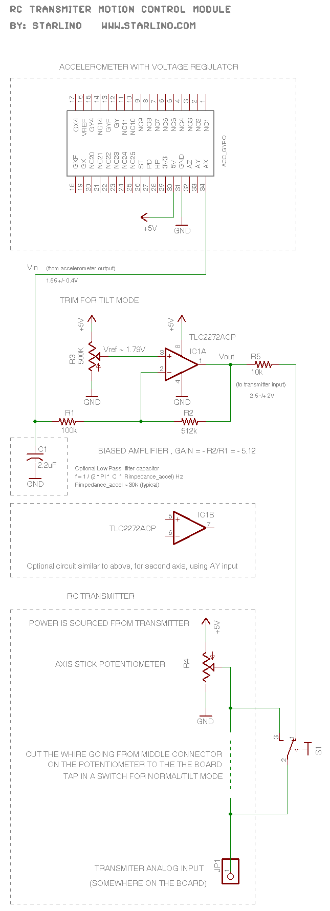
How it Works
The RC transmitter uses a potentiometer for each axis, it acts as a voltage divider sending a voltage of 0..5V (the middle position corresponds to 2.5V) to the analog input that is converted into a pule of 1..2ms that is sent over RF.
This module converts (amplifies and shifts) the accelerometer analog output , usually 1.65 +/- 0.4V to the same range of the potentiometer and sends it to the transmitter instead.
An op-amp in an inverting amplifier configuration is used. Vref is set manually by tuning the output to be 2.5V (or the PWM pulse to be 1.5 ms). However it is possible to calculate the theoretical value as follows:
Note that according to the rules of a feedback op-amp the voltage on it's inverting/non-inverting terminals tends to equalize so V(+) = V(-) and in our case = Vref.
Since no significant current enters the op-amp , the currents going through R1 and R2 are equal:
( V(-) – Vin ) / R1 = ( Vout – V(-) ) / R2
(Vref – Vin) / R1 = (Vout – Vref) / R2
solving for Vout gives us
Vout = Vref – R2/R1 (Vin – Vref) = Vref( 1 + R2/R1) – R2/R1 * Vin
now let's do some notations
G = – R2/R1
Vout = Vref( 1 – G) – G * Vin
According to our schematic G = R2 / R1 = – 5.12 , this will convert the accelerometer swing of 0.4 V to a swing of 0.4 V * 5.12 ~ 2V .
We want to make Vin = 1.65 correspond to a Vout = 2.5 so we have the equation
2.5 = Vref (1 + 5.12) – 5.12 * 1.65
from here we find
Vref = (2.5 + 5.12 * 1.65 ) / (1 + 5.12) = 1.78888 V
Well, this is the theoretical value , in practice we adjust the trimmer R3 until the output is 2.5 while the accelerometer is in laying in horizontal position (has an output of 1.65V).
How to Build
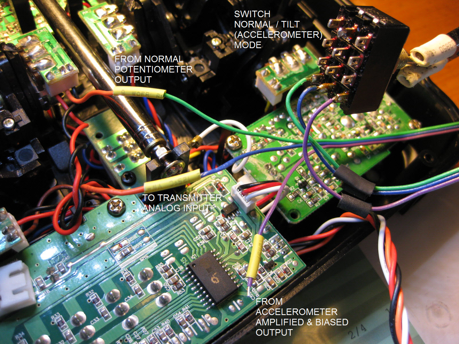
To build use a small proto-board following schematic. Part numbers are mentioned on schematic. Hook-up with the transmitter is described in images below and on the schematic. For accelerometer use Acc_Gyro or similar module, or build your own accelerometer break-out board.
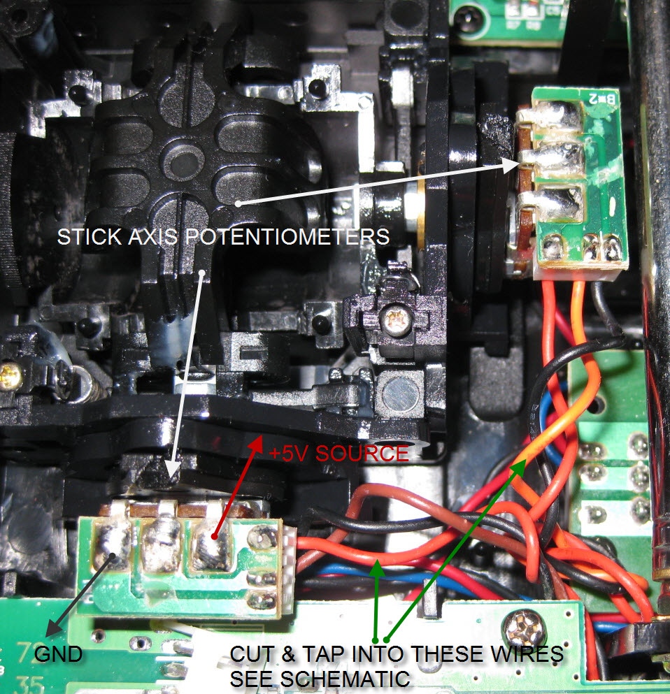
The module is mounted in a free space under antenna using double-sided foam tape – best way to mount an accelerometer to avoid vibration. Note that we get +5V power for the module from the potentiometer contacts. You can test with a led that the power contacts can deliver at least 20mV, the module uses far less <5mA.
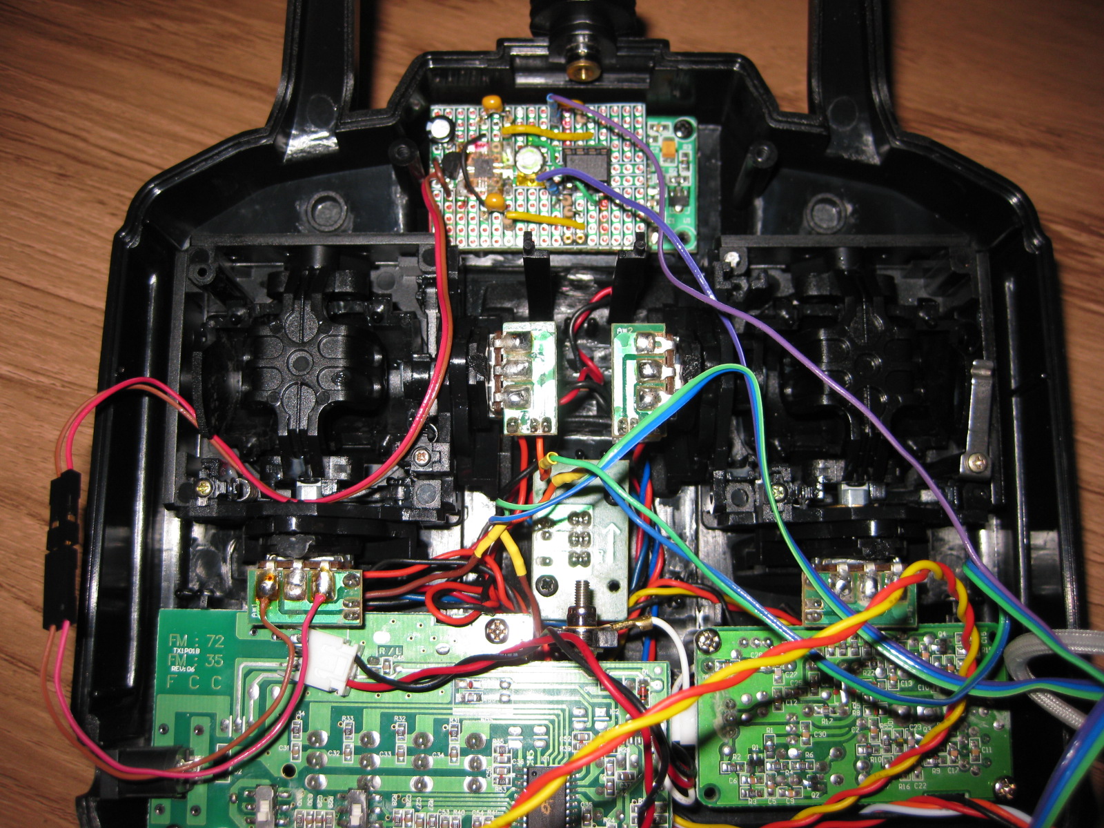
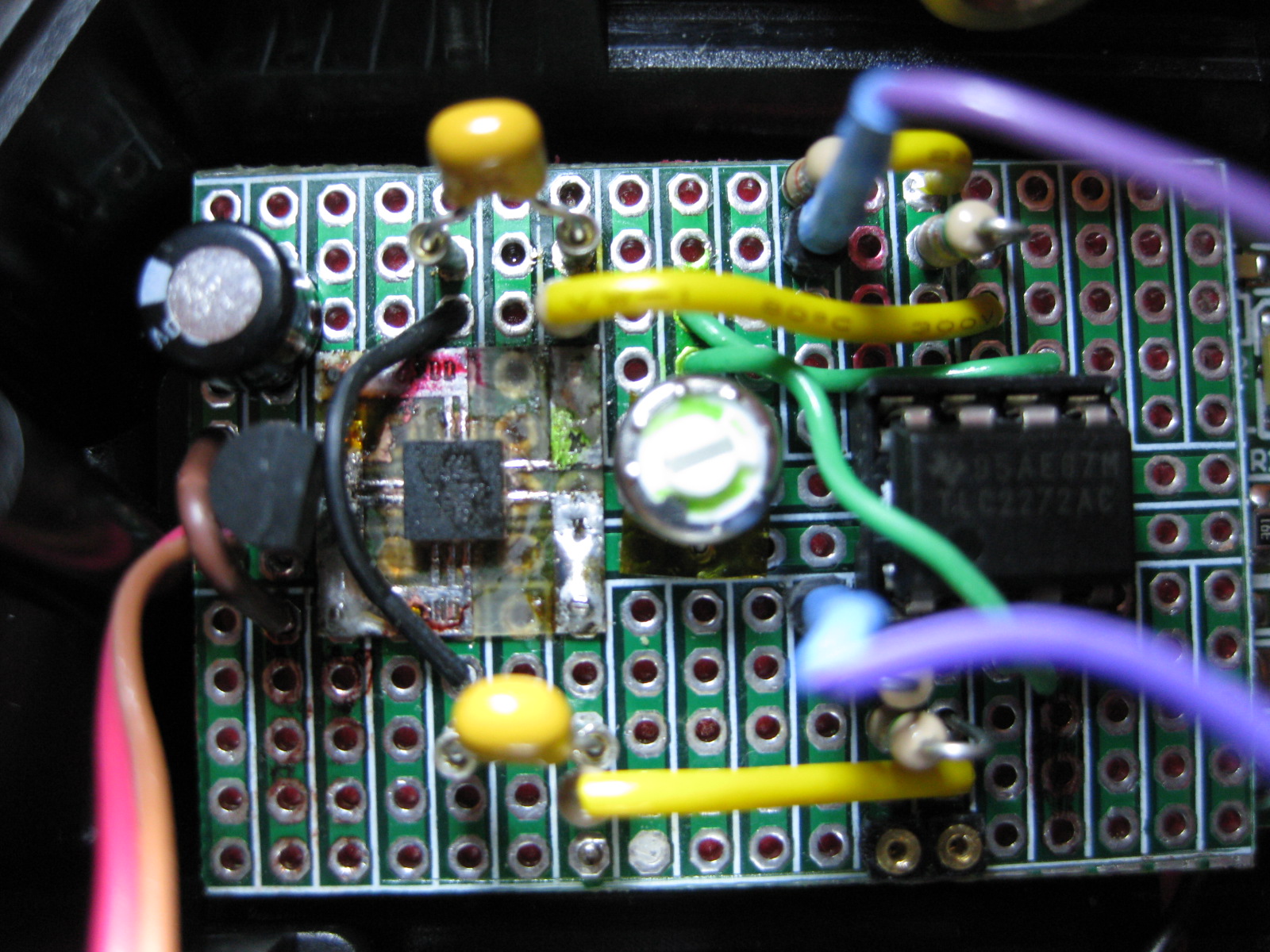
Here is a close-up of the module, as you can see I did my own accelerometer break-out board, but you can buy a pre-assembled one , there are many choices. You will need an analog accelerometer for this project.
Enjoy your new RC Tilt Transmitter. For any comments/questions use the comment form below.
//starlino//
Pingback: Adding motion control to an RC transmitter - Hack a Day
I have a question…
have you ever done an encoder with a microcontroller? I want to do one and I need people that knows the matter to start…
we can support each other..
Thanks
Hi, I have a question about your motion tilt control. I’m relatively new at diy electronics/schematics, but does having two axis here require two TLC2272ACP circuits?
Also, in your close-up image of your circuit, are you handling voltage regulation yourself since it’s a homemade accel. breakout?
Thanks in advance,
Evan
Evan , yes I have a 3.3V voltage regulator that regulates the existing 5V power from transmitter. This regulator is the TO-92 part you see on close-up. I can also suggest acc_gyro board since it already has voltage regulation.
TLC2272ACP is a dual op-amp so you don’t need 2 parts, just one just use the other inputs/outputs. See datasheet here:
http://focus.ti.com/lit/ds/symlink/tlc2272a.pdf
One problem I had with this particular design is that when the antenna is fully extended the circuit picks up a lot of noise (72Mhz), that was somewhat reduced by connecting voltage regulator directly to the battery (12V) and winding the power wires on a ferrite coil.
Thanks for the help starlino, would you happen to have source file for the schematic?
Thanks, Evan
Here are the eagle files : http://www.starlino.com/data/rc_transmitter_accelerometer/RcTransmitterAccelerometer.zip
(the brd is un-routed), this design uses acc_gyro (http://gadgetgangster.com/213),
I want to make rc tx like that too. our idea is same and i think we have same problem to:just move elevator and aileron, cannot move rudder. so I think I have to use gyro. nice share ;)
Aang, that’s nice! If you ever document or blog about your project , please let us know it would be something interesting to look at.
Starlino, great success! I have my tx working in both axis from the accelerometer, the only thing is I want to have one axis follow the side to side rotation of my head (fpv style) instead of tilting F to B and L to R. Any suggestions?
We could take this to RC Groups if you’d like.
Thanks again, Evan
Perfect, but could i use this just to steer a single servo, which would be on the z-axis? And possibly use the x-axis for servo jack (to rise my 24 scale 1965 Pontiac GTO Hurst edition). I will need a switch to enable/disable the jack and a separate switch enable/disable the steering tilt control (z-axis).
Is this the board you suggested?
http://gadgetgangster.com/find-a-project/56?projectnum=213
or would that be to much? I don’t think it will fit in my 8303 Jaguar.
Also, my 8303 Jaguar controller runs on 8 AA batteries.
Could you please explain how i would have to convert the voltage.
i make rc subs this is great way to control the boat do you have project a accle controling a servo stand alone.thank you for your time. alf
hi. i saw your project and liked it very much. can i use this setup for a rc helicopter? i have two gyro that i can use but do not understand how to put them in place. if you can help please let me know. thanks very much. julian
hello starlino, i like your tilt motion transmitter. do you think it will work with a rc helicopter? i will like to use the mma7260 accelerometer. thanks for your help. jay
hi jay, I think it will be too sensible and will take a while to get used to. I would use a simulator to train to the motion control first, also have a switch like I have for emergency switch to normal control
thanks for your reply so soon starlino, i was thinking about that, but i do have a receiver with gyro built in, i think that will help to keep it more stable. are you sending the two axis from the acclerometer into one input on the [trans]? tahnks again jay
typing too fast, thanks again jay
hello starlino, i am having a little problem with my project. i installed my accelerometer into the [trans] but i do not have the right output voltage on axis X&Y i think the voltage should be 5v max and 2.5 volt to start with, the [acc] output is 2.3v max on axis x/y. i need more output from the [acc] can you please help THANKS, JAY
hello starlino, i have a question, what is R2 on your tilt rc transmitter circuit. i am having a hard time finding a 512k resistor. can any one help? thats all i need to complete this project. THANKS
Jay, you can use a 1M trim pot instead of R1/R2 – the ratio between R2/R1 will give the gain of the amplifier as mentioned on schematic.
starlino, are you saying to use a 1M ohm trim pot instead of R2 and set it to [512k]? i am not a pro at this, any help will be great. thanks
yes you can use the pot to replace the 512k resistor or
you can use it to replace bot R1 / R2 and set the pot to the 1:5 Ratio for example 170K / 830k (170+830 = 1000k = 1M)
Jay it looks like you have some pretty basic questions , may I recommend a book that helped me get started with electronics:
http://astore.amazon.com/librarian06-20/detail/0071452818 Best $20 you’ll ever spend.
starlino,i don’t mean to be a pain,but it’s hard to see that resistor color codes on the photo, maybe i will just buy the book. JAY
hello starlino, I got my tilt mode transmitter completed and i am happy to say it is working very good. thanks for your help, I’ll try to use it on my rc heli and see what happen. i will let you know soon. jay
Starlino————–is there a device for 'trigger style' rc controllers?
Does this setup is available for purchase?
If yes, please let me know the price. We would like to customise the titling angle programatically.