
Demo
Introduction
I recently built a new Media PC for my living room. It runs on a Pentium M CPU (normally used in laptops) that draws very little power. Although many Media PCs already come with some sort of remote control (the case I used also came with a remote control) I find that using a wireless mouse is more convenient and can be used with all Windows application.
For my my Media PC remote control I wanted to use as few remote control devices as possible. I settled that to use a cheap wireless mouse and the TV remote control that I use anyway when watchign TV.
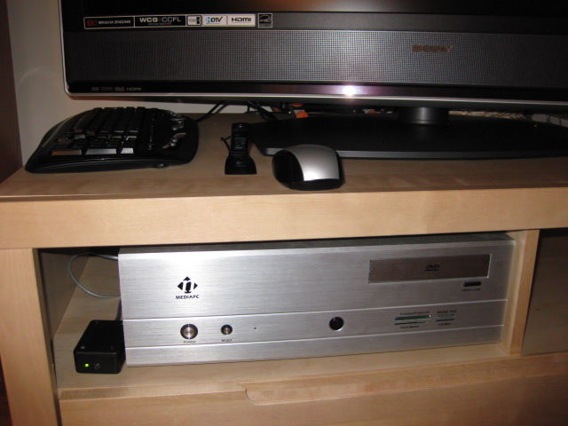
My Media PC setup – the device described in this article is in the left bottom corner (the black box).
The keyboard shown on the pictured is wired and I don't use it for remote control. You can type on your computer using a wireless mouse. Windows has a little known application called On-Screen Keyboard. It can be started by going to Start > Run and then typing osk in the Open: dialog. You can also create a shortcut on your quicklanch bar so you can easily start this application using your wireless mouse.
.
Windows osk application allows you to type text using a mouse
My initial setup that used my Sony TV Remote and Wireless Mouse had one single remaining problem – there was no way to turn on the Media PC remotely. This was my motivation to build a simple low-cost device that would simulate the press on the computer power button when it received a predefined sequence of codes from the TV Remote Control.
Circuit
The circuit presented below uses a 38kHZ IR Detector to read the pulses sent from a Sony IR Remote Control. When a certain combination of keys was pressed on the remote it activates the relay which is connected to the PC power switch.
Parts
To save you some time I will only mention that the 38kHZ IR Detectors can be purchased at the following retailers AllElectronics , Parallax , Radioshack . Please note that although these detectors are similiar – they have diiferent pinouts, so consult the datasheet before using them! I only tested the detectors sold by AllElectronics and Parallax – they work the same, they even seem to have a similar range. The relay I used is a 5VDC REED RELAY from AllElectronics grab one if you'll be ordering the IR detectors from the same retailer. The other parts including the PIC microcontroller are realatively easy to find so I will not point to any specific stores.
Code
For this project I used a PIC18F1320 microcontroller there is no specific reason for this choice – I just had one available . If you are familiar with programming microcontrollers feel free to substitute this microcontroller with another one that you might have available. The program is simple so you should be able to adapt it even to a different programming environment. I've done my first experiments on a Basic Stamp II and then migrated the code and circuit to PIC in order to reduce the cost of the project.
For this project I'm using the Picbasic Compiler. My choice was based on the fact that Picabasic has the PULSIN command that proves to be very useful for detecting the IR pulses. In the code presented below the device is programmed to activate the relay for a period of 2 seconds only when two codes are received from the Sony TV Remote in exact sequence: 54 (SLEEP) and then 58 (DISPLAY). You don't have to press both keys at once. Just press one key, followed by the other one.
The keys have been chosen based on the fact that they should not have a bothersome effect for the TV viewer if received by TV. For example if I would have used one the number keys the TV would change channels while I try to turn on the PC. SLEEP and DISPLAY keys will only display some information if pressed just once, (pressing SLEEP more than once will actually activate the SLEEP mode, but I only need to press it once and that will just display the current sleep mode). Your TV set might act differently so choose your own combination !
Also I assumed that I would not normally press this sequence of keys accidentally. If you're paranoid that this might happen and your PC might turn off, or if you would like to have a stronger secret code and disconenct the front pannel computer switch as described in Suggested Modifications section, I suggest that you modify the program to use a longer sequence of keys. In Anex 1 you'll find other Sony Remote Codes that I determined experimentally on my Sony Remote.
'——————————————-
'THESE ARE DEVICE SPECIFIC CONFIGURATIONS, IF YOU'RE USING ANOTHER PIC YOU WILL HAVE TO CHANGE THEM
'PLEASE NOTICE MCLRE IS OFF (THUS NO NEED TO USE A RESISTOR CONNECTED TO MCLR(VPP) PIN IN CIRCUIT ABOVE)
DEFINE OSC 4
'If you get "Overwriting previous address contents .."
'Comment out these settings in PBP/18F1320.inc , or modify them dirrectly in that file, it gets included automatically in your program
@ __CONFIG _CONFIG1H, _INTIO2_OSC_1H
@ __CONFIG _CONFIG2H, _WDT_OFF_2H
@ __CONFIG _CONFIG4L, _LVP_OFF_4L
@ __CONFIG _CONFIG3H, _MCLRE_OFF_3H
OSCCON = $62 'set clock to 4Mhz
'——————————————-
pinIR VAR PORTB.5
TRISB.5 = 1 'INPUT PIN
pinLed VAR PORTB.1
TRISB.1 = 0 'OUTPUT PIN
pinRelay VAR PORTB.3
TRISB.3 = 0 'OUTPUT PIN
irPulse VAR Word
remoteCode VAR Byte
lastCode VAR Byte
'——————————————-
LOW pinRelay 'UPDATE BUG FIX: 1/14/2009
HIGH pinLed
lastCode = 255
PAUSE 500
'if 4MHz oscillator is used, the pulse width is returned in 10us increments
DEFINE PULSIN_ MAX 5000 ' wait 50 ms max
i VAR Word
start:
HIGH pinLed
remoteCode = 0
'wait for "start pulse" ~ 2.4 ms
RCTIME pinIR, 0, irPulse
IF irPulse < 200 THEN GOTO start ' < 2 ms
'now read bits , "0" ~ 0.6ms , "1" ~ 1.2 ms
'WHILE(pinIR): WEND 'THESE STATEMENTS CAN BE USED INSTEAD OF PULSIN
'RCTIME pinIR, 0, irPulse 'TESTED AND IT WORKED
'you can also put the following in a loop, but you'll be wasting CPU cycles, timing is critical here
PULSIN pinIR, 0, irPulse
IF irPulse=0 THEN GOTO start
IF irPulse > 100 THEN remoteCode.0 = 1 '> 1 ms
PULSIN pinIR, 0, irPulse
IF irPulse=0 THEN GOTO start
IF irPulse > 100 THEN remoteCode.1 = 1
PULSIN pinIR, 0, irPulse
IF irPulse=0 THEN GOTO start
IF irPulse > 100 THEN remoteCode.2 = 1
PULSIN pinIR, 0, irPulse
IF irPulse=0 THEN GOTO start
IF irPulse > 100 THEN remoteCode.3 = 1
PULSIN pinIR, 0, irPulse
IF irPulse=0 THEN GOTO start
IF irPulse > 100 THEN remoteCode.4 = 1
PULSIN pinIR, 0, irPulse
IF irPulse=0 THEN GOTO start
IF irPulse > 100 THEN remoteCode.5 = 1
PULSIN pinIR, 0, irPulse
IF irPulse=0 THEN GOTO start
IF irPulse > 100 THEN remoteCode.6 = 1
LOW pinLed
'combination to turn on the relay
IF lastCode=54 AND remoteCode=58 THEN 'SLEEP , DISPLAY
HIGH pinRelay
PAUSE 2000
LOW pinRelay
ENDIF
lastCode = remoteCode
PAUSE 50 'keep led on
GOTO start
'——————————————-
Please note that this code will only work with Sony or compatible remote controls. If you happen to have a different remote control I suggest that you do some research about the protocol it uses and modify the programm accordingly. If you happen to have one of those universal remote controls try to programm your univrsal remote to send a sony code, because your TV is not Sony you might even use a single sony code (for instance POWER code 21) that will be ingnored by your non-Sony TV but will be captured by this device.
Theory
So how does it work ? The principle of opperation of this device is very simple: when you press a button on your remote , it sends a series of pulses that are detected by the IR detector. The IR detector is sensible only to frequences close to 38kHz so that other infra red emiters would not interfeer. The output signal of the IR detector is normally HIGH (1). Each code starts with a long pulse of 2.4ms, binary "0" is encoded as a pulse of 0.6ms, binary "1" is encoded as pulse of 1.2ms.
Our code loops untill it detects a pulse that is longer than 2ms (that's got to be the 2.4ms starting pulse). For our microcontroller RCTIME command returns values in 10uS increments (you can read about this in the compiler manual) thus we compare against the value of 200 (2ms / 10us = 200). Note the first parameter of the RCTIME command is 0, this means that we are looking for the signal to go LOW(0) and we measure how long it stays low.
start:
…….
'wait for "start pulse" ~ 2.4 ms
RCTIME pinIR, 0, irPulse
IF irPulse < 200 THEN GOTO start ' < 2 ms
Once a start pulse has been detected , without waisting too much time, we read the next 7 pulses and get the first 7 bits of our code. Once we have our code we check the current code and the previous code and if it matches our combination we turn on the relay for 2 seconds. This would be equivalent to holding the switch button of the computer for 2 seconds. This is the part of the code that you would modify in order to change the key combination (check the codes for various keys in the Anex 1)
'combination to turn on the relay
IF lastCode=54 AND remoteCode=58 THEN 'SLEEP , DISPLAY
HIGH pinRelay
PAUSE 2000
LOW pinRelay
ENDIF
lastCode = remoteCode
PAUSE 50 'keep led on
GOTO start
Please note that the PAUSE 50 is added here in order to make the led blink when a key is being pressed. This proves to be usefull in order to give the user a visual feedback that the signal sent from remote is being received and decoded. After we store the current code in the lastCode variable we jump back to the start label and wait for another code.
Construction
I chose to place my device in an external enclosure. This might also be your choce if your PC is innacessible for the IR beams or you don't want to drill any openings in the frontpanel of you computer for the IR detector and the led. However you'll still need a small opening in your case to route the wire, you can usually find plenty of openings at the back of the case used for ventilation. Be careful not to route the wire close or through a fan opening!
This device can also be placed inside the case of your computer, this would be a more elegant solution for a Media PC. However you will need to create openings in the frontpanel for the IR Detector and optionally for the activity led. Your Media PC case might already have an opening for the IR detector. Mine actually has it, but I didn't use it. Remember Infra Red light will not pass through any solid materials, they need an unobstructed line of sight to the remote control IR emiter.
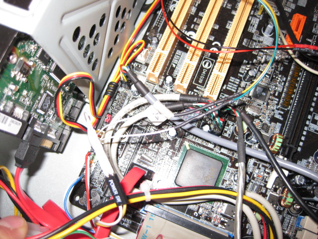
To power the device I used the PC ATX Powere supply. Even when your computer is turned off the power supply provides 5V on it's purple wire. To tap into the power supply wires I removed the insulation from the purple(5V) and one of the black(Ground) wires and then connected my wires that power the device. If you don't want to alter the cables on your power supply (as this might void your manfacturer warantee), I suggest that you use an ATX power supply extender and then you can tap into its wires. Another alternative is to use a different power supply altogether, like a 5V DC wall power adapter.
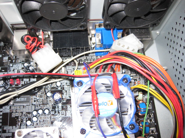
Taping into power supply wires. The purple wire gives you 5V even when your PC is off. The black wire is ground.
Here is the actual device that I've built. I like to separate some subcircuits that I might "borough" later and use for other projects. Notice that the relay suncircuit is separated on its own little board. The device box is connected to the PC case with a regular 4 wire phone cable. Two wires (black and wite) are used to power the device from the ATX power supply as described above and the other two wires (green and yellow) are connected at one end to the relay and at the other end to the Power Switch header on your motherboard.
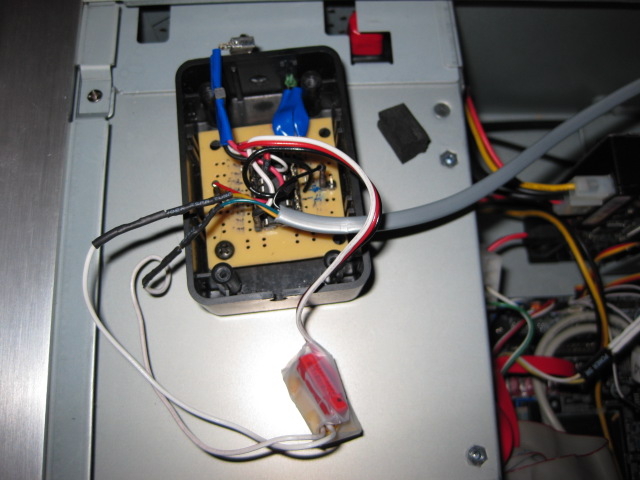
IR Detector(top left), Green Led(top right) , PCB with PIC (middle), separted Relay Subcircuit (bottom)
If you're having trouble finding the Power Switch header on your motherboard consult your motherboard manual. You're looking for 2 pins on your motherboard that are connected to the frontpannel power switch. These pins are usually located on the same header with other pins (like HDD LED, RESET SWITCH, SPEAKER, etc).
Connection schematic using a sample motherboard frontpanel
connector, your connector might be different !
From the schematic above you can see that the relay terminals are connected in paralel with the frontpanel power swtich so you can use both to turn on and off the computer.
I created 2 Y spliiters using crimp pin terminals and a crip tool. Then I insulated the ends with shrink tubing. If you can't create these you may choose a more intrusive solution like taping into the wires that go to you frontpanel power switch just like we did for the power supply.
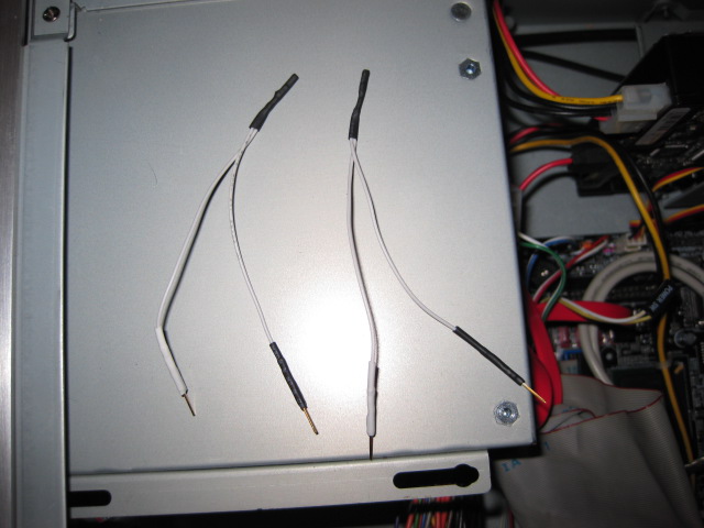
Use these Y splitters to connect both the device and the frontpanel switch to the motherboard connector
One end of Y spliiters are conencted to motherboard frontpanel header. "Power SW" ramification
goes to frontpannel switch, the other ramifications (green and yellow wires) go to device relay switch.
Suggested Modifications
1. This device can be used as a secure way to turn on your computer. Just disconnect the frontpannel switch and the remote controll code will be the only way to turn on your PC. For added security place a lock on your PC enclosure, most enclosures have holes that allow to place a small lock on side covers. For this setup I would also suggest placing the device inside the PC case, otherwsie one could open the device box and short the switch wires.
2. If the permanetely lit led bothers you, you may reverse the action of the led (it will be normally off), just replace in the code above 'HIGH pinLed' with 'LOW pinLed' and vice-versa.
3. You can adapt this device to turn on other appliances not just your PC. Just make sure to use a relay that is rated for the currents you will be switching.
4. Although I didn't try it, I suspect that the relay subcircuit could be replaced by a single transistor since we're powering the device from the PC and we have a common ground. However the relay gives you a more universal solution that can also be used to switch other appliances with higher currents going through the switch (up to the maximum rated current of the relay).
Anex 1 (Sony Remote Control Codes)
TV/VIDEO 37
SLEEP 54
POWER 21
FREEZE 92
PICTURE 100
WIDE 61
GUIDE 14
DISPLAY 58
LEFT 52
RIGHT 51
UP 116
DOWN 117
CENTER 101
RETURN 35
TOOLS 54
MENU 96
DIGITAL/ANALOG 13
JUMP 59
1 0
….
9 8
. 29
0 9
ENT 11
MUTING 20
VOL UP 18
VOL DOWN 19
CH UP 16
CH DOWN 17
Thanks
hi i am sara thank you very much
i’m univercity student and my project is this
i’m glad that you help me in this project
Pingback: please help for turn ON and OFF a relay
This is great! I’ve been looking for a way to control the power on an older amp that I have that doesn’t have remote control. I was going to try using the signals generated by the AUX device button on my remote with a micro/IR setup like this, but I hadn’t investigated the IR pulse train yet.
I’ve been using PIC micros for a few years now, and enjoy projects like this.