
Demo
Circuit
This is the schematics for a PIC USB gamepad that I have built in a steering wheel shell. The code for the firmware was written in PicBasic Pro and it implements a HID USB device with 2 axes and 4 buttons (only 2 buttons connected in the prototype). The device is detected by Windows XP/Vista as a standard USB gamepad and can be used with many games and applications.
I am using a 2 Axes Buffered ±2g Accelerometer from DIMENSION ENGINEERING, it has a built in voltage regulator that allows powering the accelerometer dirrectly from the USB bus (5V):
http://www.dimensionengineering.com/DE-ACCM2G.htm
I highly recommend this accelerometer as well as other great Dimension Engineering products, check out their website: www.dimensionengineering.com !
Note: Optionally you can connect 2 more buttons to RB2 and RB3.
Code
Below is the PIC Basic code that works both on 18F4550 / 18F2550. (There are other requirements to build USB firmware including the HID header, see compiler documentation).
DOWNLOAD HEX FILE FOR PIC 18F2550 (You will need a PIC Programmer to transfer it to the chip, I'm using PICKit2):
IMPORTANT NOTE: Please disconnect any Microchip Devices (including the PICKit2 programmer) before plugging this device since it's using same HID VENDOR /PRODUCT ID provided in Microchip sample files.
If you plug 2 devices with same VENDOR/PRODUCT ID you might get a hardware conflict and the devices might not work.
—————————————————————————————-
Define OSC 48
'CONFIGURATIONS ARE IN /PBP/18F2550.INC , YOU MIGHT WANT TO EDIT THEM
'ADC
DEFINE ADC_BITS 10 ' Set number of bits in result
DEFINE ADC_CLOCK 6 ' Set clock source Fosc/64 => TAD => 1.34uS
DEFINE ADC_SAMPLEUS 50 ' Set sampling time in uS
TRISA.0 = 1
TRISA.1 = 1
ADCON1 = %00001101 ' sets AN0,AN1 to analog mode
ADCON2 = %10101110 '
'bit 0-2: ADCS ,OVERWRITTEN BY ADC_CLOCK, 110: Fosc/64 => TAD => 1.34uS
'bit 3-5: Aquisition time: 101: 12 TAD => 16uS
'bit 6: not used
'bit 7: Right justify for 10-bit
x VAR WORD
y VAR Word
INTCON2.7=0 'RBPU =0 , TURN ON PORTB PULL-UPS
bt1 VAR PORTB.0
TRISB.0 = 1
bt2 VAR PORTB.1
TRISB.1 = 1
bt3 VAR PORTB.2
TRISB.2 = 1
bt4 VAR PORTB.3
TRISB.3 = 1
'USB
buffer Var Byte[3]
USBInit
main:
ADCIN 0,x 'read AN0
ADCIN 1,y 'read AN1
'x,y experimental measurments: ~512 @center / ~365 @ -90deg / -655 @ +90deg
x = (x >> 2) << 2 ' clear last 2 bits
y = (y >> 2) << 2 ' clear last 2 bits
'convert x,y from range [384..512..639] to [0..128..255] with edge clipping
x = ((x MAX 384) MIN 639 ) – 384
y = ((y MAX 384) MIN 639 ) – 384
buffer[0] = y 'gamepad's x-axis is accelerometer's y axis
buffer[1] = x 'gamepad's y-axis is accelerometer's x axis
buffer[2] = PORTB ^ %00001111 & %00001111 'separate and reverse first 4 bits
USBService ' Must service USB regularly
USBOut 1, buffer, 3, main ' Send buffer to endpoint 1
GOTO main ' Do it forever
—————————————————————————————-
Here is how it is detected by Windows XP. Please note that if you don't change the USB HID Vendor ID and Product ID code this device might conflict with other microchip HID devices using same indentification, including the PICKIT II USB programmer (you can't have them plugged in both at the same time).
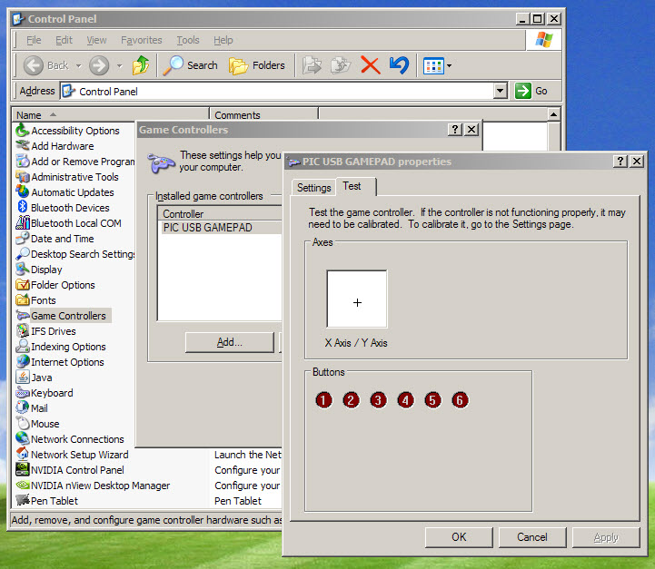
There's no need to calibrate the device on this Windows screen, since it will output values within 0..255 range for both axis and it will be centered close to 128,128 values (we took care of this in the program).
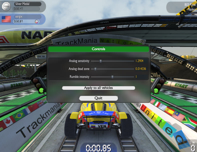
However you might want to adjust sensitivity in your game, based on your preference:
Construction
If using an existing USB cable , the wire coding is VDD red, VSS black , D+ green , D- white.
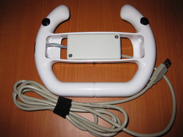
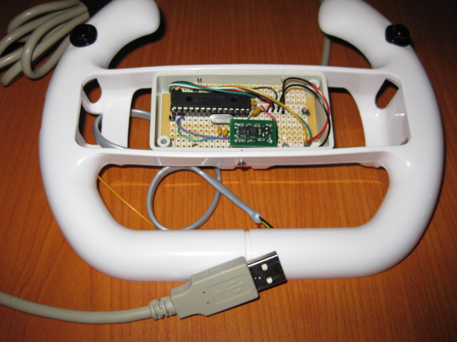
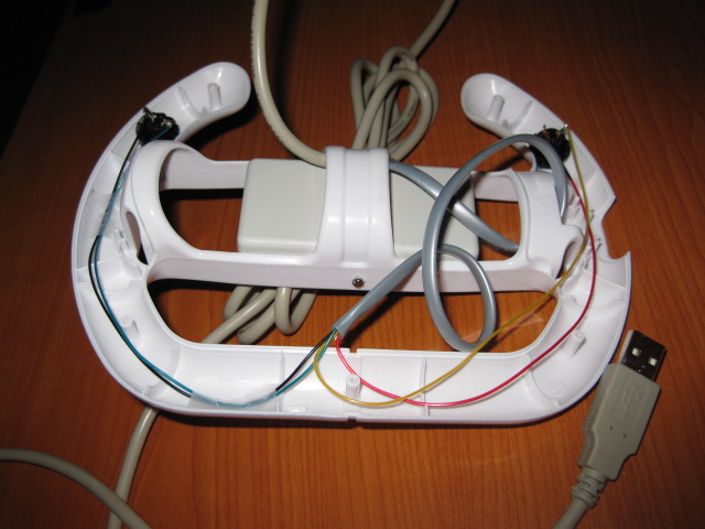
Second prototype using PIC18F2550 chip.in a cheap Wii steering wheel shell. (Look for them on EBay they sell for about $1.45).
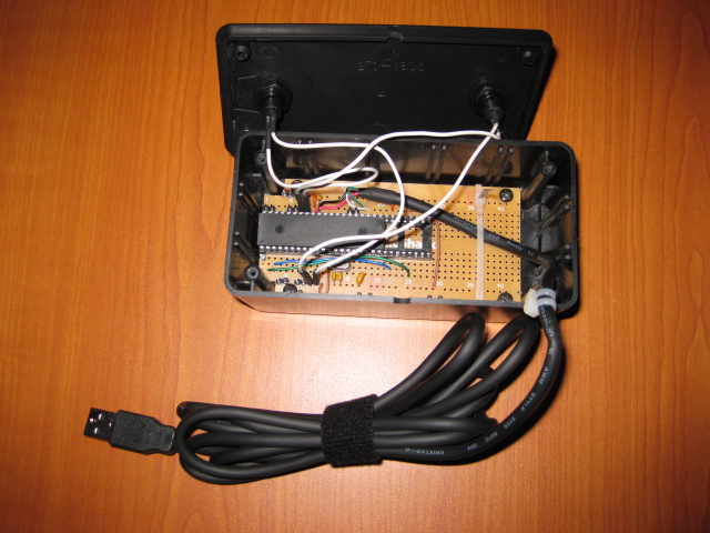
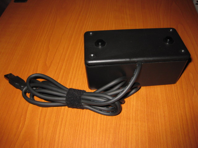
First prototype "THE BRICK" , using PIC18F4550 chip, accelerometer removed.
It can work as a motion MOUSE too !
With a slightly different firmware and the same hardware you can build a USB Motion (Tilt/Pan) HID Mouse, source code is here:
http://code.google.com/p/hidmouse/
SVN Trunk:
http://code.google.com/p/hidmouse/source/browse/#svn/trunk/%20hidmouse
Also for anyone interested in a quick build, with all parts and PCB – gamepad kits with pre-programmed PIC and accelerometer are available for 50 USD @ http://gadgetgangster.com/231 .
///starlino///
very nice work…… i would like to know where can i get the others files … usb descriptors for this project? thanks
greetings from mexico
pode me enviar o arquivo HEX para o PIC18F4550?
thanks
Yes, does anyone has descriptors for this project, they’re killing me….
Here is full source code including gamepaddesc.asm:
http://www.starlino.com/wp-content/uploads/data/usb_gamepad/18F2550_Gamepad.zip
I love you mannnn!!!!! :))))))))
Thanks for making this available this is a very cool project. I downloaded you project source and tried to compile it with mplab using pbpw.exe as the compiler but get an error, see below.
Any suggestions of what I may be doing wrong ?
Thanks,
Pete.
ERROR: Unable to execute mpasmwin.Error[113] \PBP\PBPPIC18.LIB 715 : Symbol not previously defined (USBDeviceInit)
Error[113] \PBP\PBPPIC18.LIB 716 : Symbol not previously defined (USBDeviceInit)
Error[113] \PBP\PBPPIC18.LIB 715 : Symbol not previously defined (USBDeviceTasks)
Error[113] \PBP\PBPPIC18.LIB 716 : Symbol not previously defined (USBDeviceTasks)
I forgot to ask, what compiler version are you using ?
I have….
PICBASIC PRO(TM) Compiler 2.60
Thanks.
I think I used picbasic 2.5 pro at the time, I no longer use it and switched to MPLAB with C18, C30. I have a note however here in my files: PICBASIC must be on same drive as where your project files are , for example they have to be both on C: or both on D: Also from what I recall I was using the PICBASIC IDE not MPLAB.
ok, I have it working now:-) user error! I had the two inner pins of the usb header round the wrong way ! I have another question,if its ok. Do you know how I could get RB4-RB7 as well as RA3-RA5 and RC0-RC7 to behave in the same way as RB0-RB3.
As you can tell I am new to this and appreciate your help.
Thanks,
Pete.
I forgot to say, I down graded to picbasic pro 2.5 and it compiled first go :-)
Pete to define additional buttons you just need to make sure the pins are set to to input mode.
For example:
bt5 VAR PORTA.3
TRISA.3 = 1 // button #5 connected to A3
Starlino,
Thanks for all your help. I have finally got a finished project. I was looking to replicate this.
http://www.desktopaviator.com/Products/Model_2040/index.htm
and your project was the closet I could find. I removed the accelerometer component and added 18 buttons to give a total of 20. There were a few hoops I had to jump through.
Disabling analogue on AN0 and AN1.
Disabling MCLR on pin one to use it as RE3.
I also had to mod the board to add a bunch of 4.7K resistors for stability.
I basically have what I set out to do. I could not figure out how to only have 20 buttons displayed with the HID config so I have 24, any suggestions, look at the code below for details of my changes.
I will put a summary together and post a link here to it as soon as I get the chance.
Pete.
My code below.
Define OSC 48 ’20mhz
‘CONFIGURATIONS ARE IN /PBP/18F2550.INC , YOU MIGHT WANT TO EDIT THEM
‘ turn off MCLR pin and enable RE3 by appending “‘& _MCLRE_OFF_3H” in /PBP/18F2550.INC
‘ the line should now look like this:
‘
‘ __CONFIG _CONFIG3H, _PBADEN_OFF_3H & _MCLRE_OFF_3H
‘
‘ In the file gamepaddesc.asm change the following to remove the accelerometer
‘ portion and increase the number of buttons to 20 (the max for this PIC), the section should look like this
‘
‘
‘ retlw 0x01 ; COLLECTION (Application)
‘ retlw 0x05
‘ retlw 0x09 ; USAGE_PAGE (Button)
‘ retlw 0x19
‘ retlw 0x01 ; USAGE_MINIMUM (Button 1)
‘ retlw 0x29
‘ retlw 0x18 ; USAGE_MAXIMUM (Button 24)
‘ retlw 0x15
‘ retlw 0x00 ; LOGICAL_MINIMUM (0)
‘ retlw 0x25
‘ retlw 0x01 ; LOGICAL_MAXIMUM (1)
‘ retlw 0x75
‘ retlw 0x01 ; REPORT_SIZE (1)
‘ retlw 0x95
‘ retlw 0x18 ; REPORT_COUNT (24)
‘ retlw 0x55
‘ retlw 0x00 ; Unit_Exponent (0)
‘ retlw 0x65
‘ retlw 0x00 ; Unit (None)
‘ retlw 0x81
‘ retlw 0x02 ; INPUT (Data,Var,Abs)
‘ retlw 0x81
‘ retlw 0x03 ; INPUT (Constant,Var,Abs)
‘ retlw 0xc0 ; END_COLLECTION
‘ADC
DEFINE ADC_BITS 10 ‘ Set number of bits in result
DEFINE ADC_CLOCK 6 ‘ Set clock source Fosc/64 => TAD => 1.34uS
DEFINE ADC_SAMPLEUS 50 ‘ Set sampling time in uS
ADCON1 = %00001111 ‘Everything digital inc, AN0 and AN1
TRISA = %11111111 ‘PORTA is input
TRISB = %1111111 ‘PORTB is input
INTCON2.7=0 ‘RBPU =0 , TURN ON PORTB PULL-UPS
‘USB
buffer Var Byte[3]
USBInit
main:
buffer[2] = (PORTC.2 + PORTC.6*2 + PORTC.7*4 + PORTE.3*8) ^ %00001111 & %00001111 ‘buttons 17-20
buffer[1] = (PORTA + PORTC.0*64 + PORTC.1*128) ^ %11111111 & %11111111 ‘separate and reverse first 4 bits, buttons 9-16
buffer[0] = PORTB ^ %11111111 & %11111111 ‘separate and reverse first 4 bits, button 1-8
USBService ‘ Must service USB regularly
USBOut 1, buffer, 3, main ‘ Send buffer to endpoint 1
GOTO main ‘ Do it forever
Pete, for 20 buttons you basically need to create 4 bits of padding data (from what I recall), the “USB Complete” book has it all , you’ll find it in the Books/Tool selection or here http://astore.amazon.com/librarian06-20
If you’re designing anything USB this is a must-have.
“Advanced PIC Microcontroller Projects in C: From USB to RTOS with the PIC 18F Series” is also a good book and covers some USB in very easy to read language.
Hi!
Very nice project.
I just wonder if i can make it work under Windows7 somehow?
It should work under Windows 7 and many other operating systems , it’s detected as standard USB HID Gamepad so no special drivers are required.
I have build the accelerometer wheel, but i get annoyed when in my Control Panel > Game Controllers the device gets recognized by the name of “PIC USB GAMEPAD”, if someone can show me how and where to change that name into “Drive Wheel” it will be a lot of help.
Thank you, and awaiting your responses on my Pic Name problem issue.
this string is in USB descriptor in strings sections , if the string length modifies you might have to update some other variables with the new string length, to make it easy you can just pad the remaining space with spaces .
nice one . can u please send whole project details ..i would like to try it .
Hi,
The link to your ministore is not working. I would be interested in buying a preprogrammed chip.
Sorry, the pre-programmed chips are no longer available but for few extra bucks you can get the entire gamepad kit here: http://gadgetgangster.com/231
I’m interested in the mouse code. Is there any way you could include LCD code in it?
I’ve been trying to do something similar on AVR with C code, the ADC of the microcontroller is responding to accelerometer inputs but there is no mouse movement. See here:
http://www.avrfreaks.net/index.php?name=PNphpBB2&file=viewtopic&p=794724#794724
where i can get these components and the game pad
Pete I also am trying to do the 20 button version on pic 18f2550 but with no luck could you send me your hex as I see you’ve been successful bro Im at shinobiischilling@gmail.com
I would really appreciate it thanks
excellent work dude
hats off for u…..
i liked u r project and i started making it .i am almost half a way ..so can u pls get complete details (like u r report on project ) it will be helpful to me. pls help me out
Hi, What is the design changes I have to do if i build mouse with the PIC 18f4550?
no design changes for mouse device , except I guess you only need 3 buttons
how do i configure my pc to use it as a mouse_? which steps may I do for it to be recogniced as a mouse_? thanks in advance!
To use it as a mouse compile the project in MPLAB:
http://code.google.com/p/hidmouse/
For PicBasic Pro you can use the mouse descriptor provided as sample in USB stack.
You don’t need to do anything on PC, once you load the mouse firmware on device it will be detected as a standard HID mouse, no special drivers required.
so I dont have to make any changes to the code? which of the files on the 18F2550_Gamepad file do I compile and how? escuse me for all this cuestions but I have not any idea on how to make it work as a mouse, I could make it work as a game pad but I dont have any idea on how to make it as a mouse could you be more especific on the steps to make it become as a mouse_?. thanks in advance
Starlino how do I load the mouse firmware on device ?
Hi Starlino. I’m building the gamepad using the 4550. It’s gonna have 8 buttons only (i.e 4 directional,1 select, 1 start, and 2 action buttons) I’m also looking to throw in an LED that lights up when the pad is connected to the host system. Are there any warnings on the physical design of the pad? Also, do I need the external oscillator?
would u please provide the same code for AVR, it will be very helpful if u
Thanks a lot for the code!
I’m trying to build the same thing, but using 10 bit resolution (0 to 1023 steps). I tried messing with the code but with no success. Do you have any tips?
To Starlino,
Hi.Just want to know,below is my altered HIDDesc.I’m learning about USB & i wanted to make a joystick with throttle,x & y axis & 6 buttons.Unfortunately it’s not working.Can you help me out.
The HID Desc:
; retlw 0x05
; retlw 0x01 ;usage page (Generic Desktop)
; retlw 0x09
; retlw 0x04 ;usage (joystick)
; retlw 0xa1
; retlw 0x01 ;collection (application)
; retlw 0x05
; retlw 0x02 ;usage page (Simulation Controls)
; retlw 0x09
; retlw 0xbb ;usage (Throttle)
; retlw 0x15
; retlw 0x00 ;logical minimum (0)
; retlw 0x26
; retlw 0xff ;logical maximum (255)
; retlw 0x75
; retlw 0x08 ;report size (8)
; retlw 0x95
; retlw 0x01 ;report count (1)
; retlw 0X81
; retlw 0x02 ;input(data,var,abs)
; retlw 0x05
; retlw 0x01 ;usage page (Generic Desktop)
; retlw 0x09
; retlw 0x01 ;usage (pointer)
; retlw 0xa1
; retlw 0x00 ;collection (physical)
; retlw 0x09
; retlw 0x30 ;X-Axis
; retlw 0x09
; retlw 0x31 ;Y-Axis
; retlw 0x95
; retlw 0x02 ;report count (2)
; retlw 0x81
; retlw 0x02 ;input(data,var,abs)
; retlw 0xc0 ;end collection
; retlw 0x05
; retlw 0x09 ;usage page (button)
; retlw 0x19
; retlw 0x01 ;usage minimum (button 1)
; retlw 0x29
; retlw 0x06 ;usage maximum (button 6)
; retlw 0x15
; retlw 0x00 ;logical minimum (0)
; retlw 0x25
; retlw 0x01 ;logical maximum (1)
; retlw 0x75
; retlw 0x01 ;report size (1)
; retlw 0x95
; retlw 0x06 ;report count (6)
; retlw 0x81
; retlw 0x02 ;input (data,var,abs)
; retlw 0x95
; retlw 0x04 ;report count (4)
; retlw 0x81
; retlw 0x03 ;input (constant,var,abs)
; retlw 0xc0 ;end collection.
Hi Starlino,
Great Project. Can you upload HID mouse source code again?
It is no longer available at google code.
Thank you.
Sage: code is still there, just check, you need a SVN client program to download it.
Nice project :) But I am encountering a problem:
I made the above circuit and uploaded the .hex file (you gave above in the link) in my 18F2550. Everything is done but still when I connect it to my computer(Windows 7), it does not detect any device. Kindly advice.
[I am using a 3-axis accelerometer(ADXL335) connecting only 2 pins of it. Is that a problem? If yes can you tell how to implement it using a 3 axis accelerometer.]
Thanks.
Hi Starlino,
With respect to my earlier comment:
It now shows “USB device not recognised”
Aakansh check your hardware to be sure hardware is ok try another firmware for same chip and see if it works
Starlino,
Thank you very much. I downloaded via SVN client.
Hi Starlino,
I programmed to 18F2550, and it works fine.
How do I invert X direction? I would like to make pointer goes up when I raise the device.
I appreciate your advice.
Thank you.
Sage you can just flip the mounting of the device or use the configuration utility PC software to invert axis.
Starlino,
Sorry I mean invert Y direction (not X).
Starlino,
I flip mounted the accelerometer.
Very simple, now it is working as I expected.
Thank you for your advice.
Hi..
i recenty finished this project… burned the hex file using PICpgm and a serial port programmer, but the device is not working..can u help me wat problem it might hav???
also can u tel me if .47uf capacitor is equivalent to 470nf used here..????
plz reply asap
Hello
Thanks so much for your firmware
but i’ve got a little probleme if i let the module plug to my computer it’s only recognize if i unplug it twice or if i used the firmware of the other with gyro , ther no probleme i can let it plug , start my computer and no problem is there something to fix in your code
Thanks
dardard: did you try on a different computer. Also use USB Device View utility ( http://www.nirsoft.net/utils/usb_devices_view.html ) to review/delete inactive USB devices in system cache. They might have same VID/PID and conflict with your device.
on an other computer it’s working , it’s strange because on this computer i remove all usb peripherical and the problem still there , i want to compil your code but i don’t use good compiler what did you use ? ( i’ll try with a pci usb card with an other chipset to see and after try to recompil by change VID/PID) thanks for your quick answer
I use your board to a VIRTUAL PINBALL to simulate “NUDGE” that the reason why i need it recognize on the starting
Sometimes when you have the PICKit programmer plugged in it might interfere with the device. Try changing the VID/PID and see if that helps. Also remove your programmer to see if this is the case. Currently I use C18 compiler from Microchip.
I don’t have a PICKIT
Finally i put a PCI USB CARD i now it working
probleme resolve why need this perhaps a compatibility with my mainboard
Thanks it works very well
i try to compile it with mplab but with no luck
Gamepad.o is out of date perhaps a folder acces problem
can you compile me it with an other VID/PID please
Finally got it compile
It’s works with PICPRO 2.5 an MPASM 5.2
now i try to find where i can change the PID/VID
can you help me
Thanks
LOL it’s in the sotf for progamming my 18f2550
no it’s not here if you can tell me finally lol
Hi Starlino…
I’m building a project where in I’ll mount the accelerometer on an RC car… wherein it acts as an impact sensor that will record the angle of the force and the force and send it to a computer or phone.
I wish to apply your idea on how you programmed the accelerometer… and its almost near in comcept…
well sorry for my bad english
Now no probleme to compil great
i just want to add a Z axis on pinout AN2
Is it possible , i try a lot a thing but always fail
thanks
Pingback: aide pour rajout d'un axe Z sur code source - Forum modelisme.com
Can we use MikroC to replace PBP?
thanks
could send me the file of 18F2550
grateful
marcos:
http://www.starlino.com/data/usb_gamepad/18F2550_Gamepad.hex
Hey Starlino, really great work. i want to use it as HID mouse, can you send me complete source code for it. thank you.
can you send me complete source code for it. thank you.
is there any other codes which have to be loaded into the PIC chip except hex code given on your site for the usb game pad ? plz rply as soon as u can. its urgent.
The hex file contains all configurations bits. So it is the only thing that needs to be loaded on the PIC.
hi..
i tried to implement mouse using pic18f4550.
i programmed the chip. when interfacing with pc it shows
usb device unknown..
what might be the problem
yedhu: check your hardware connections. For beginners to rule out any hardware problems I recommend getting a tested hardware platform such as UsbThumb .
Starlino : When I try to compile your HID mouse code with MPLAB IDE 8.88, I get a syntax error on the following line
unsigned char hid_report_in[HID_INT_IN_EP_SIZE] IN_DATA_BUFFER_ADDRESS_TAG
Any suggestions as to what might be causing it? I have already linked the missing header and usb configuration files using the Microchip Application Libraries as a reference.
I believe when I re-created this project about a year ago, I also had "USB device unknown" when it was plugged in. If memory serves me, I believe the schematic above shows the D+/D- lines reversed…either that or I just reversed them myself by mistake!
Pingback: Homemade USB Joystick :: RessJoys 1.0 | Fairybotics
Hey! Awesome work!
I build one. Now I want to go further and want to make it wireless to use with my laptop. How can I do that? Please help!
thats really cool sir. How can we do the same thing with atmega 16? Also what is the use of these lines:-
'USB
buffer Var Byte[3]
USBInit
Hello @starlino
I have succed the Project the Probleme is How to Get a vibration motor / Output to Pic controller
Hi Starlino
what if using ADXL335 sensor, does this work?
Great project Mr.Starlino.Can I add analog joystick and 2 more buttons? great project for VR controller
Hello!
This place still alive? :) Anyway, I am curious as Rudy already asked, would it work with more modern ADXL335 modules? I guess it would, they also have analog outputs (but 3 axis), maybe I will just order and try.
Another question, is there maybe successor to this project somewhere? More axis, more buttons, etc? I know "EdTracker" for axis, but would be interesting in combinations with lots of buttons :) Thanks!
Sir can I use GY273 instead of ADXL335??
Plz help me…
thanks for this website (Starlin electronics)
plies , sear
I need a programmer to PIC18F4550 ( hex file )