
I have received some feedback from my readers regarding my first usb gamepad project , so for the past few weeks I was working on a new imrpoved design. There are plenty of new improvements that I hope will address many of your requests.
Release Notes / Change Log:
——————————————
2009-09-25
Config Utility Version 1.0.0
Device Firmware Version 1.5
——————————————
– device supports a wide range of accelerometers and gyroscopes
– implements smoothing filtering algorithm
– implements algorithm for combining gyroscope and accelerometer data
– HID USB interface makes the device compatible virtually with all modern operating systems (Mac,Windows,Linux)
– configuration utility (for Windows only for now)
– adjustable smoothing and scale factor for outputs
– configurable sensibility for accelerometer and gyroscope (can be set per axis)
– configurable midpoint (0g voltage) for accelerometer (can be set per axis)
– auto-find gyroscope midpoint (0 deg/s voltage)
– you can use separate accelerometer/gyroscopes for different axis
– Z axis not implemented in this release
– configurable analog input ports AN0-AN5 for each axis (please note 18F2550 does not have AN5 input , but 18F4550 does)
– ability to invert axis
– capture output and raw adc data into a comma separated values file (.csv)
– charting feature of all inputs/outputs
– graphical display of output and buttons
– supports up to 8 buttons
– configuration is stored in device EEPROM
– it is possible to use accelerometer alone on any axis (1, 2 or 3-axis) in this case set Smoothing to 0-10 value
– it is possible to gyro alone on any axis (1,2 or 3 axis) in this case set Smoothing to 100-255 , please note that the output will snap to middle after a while since gyro only provides rate information
– it is possible to use to use gyro and accelerometer on any axis (RECOMMENDED) in this case set smoothing to 20-100 value
– you can use multiple accelerometers or gyroscopes
– you can orient gyro or accelerometer as you like (but aligned to 90 degrees increments)
– you can connect your gyro and accelerometer outputs to any of the AN0-AN4 ports (for PIC18F2550).
Suggested Circuit Schematic
Below is a new suggested schematic , using a 2-axis Gyroscope and an a 2-axis Accelerometer. As mentioned above the new firmware and configuration utility is very flexible regarding the way the gyro and accelerometer are connected (this is one of the features requested , to be able to use device with various MEMS sensors).
Configuration Utility
Here is a screen shot of the configuration utility, please note that I am using the gyro just for one output axis (X), thus I set smoothing to 50 as recommended in release notes above. The other axis (Y) uses just accelerometer data so Smoothing is set to 5. Device automatically detected the Gyro midpoint to be 1.35V , you must hold device still for at least 1s to let it calibrate when you plug it in. The Gyro axis is also inverted due to the way it is mounted in the case.
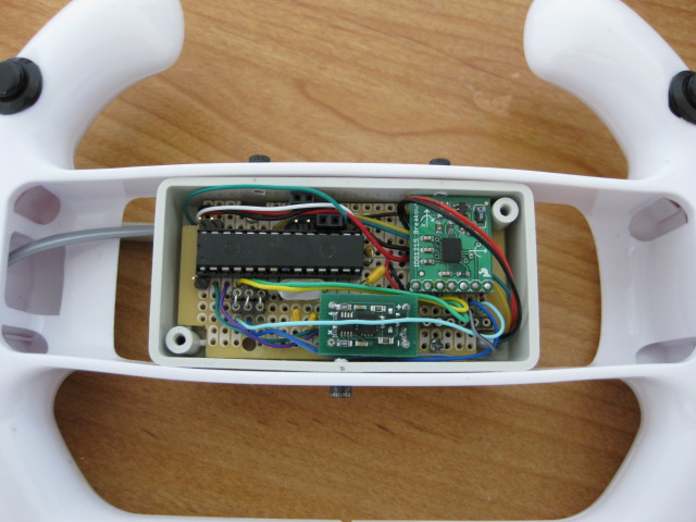
Hardware Setup
My old accelerometer-only device , got modified to make space for a gyro. Here is how it all fit inside the case:
Demo
Finally here is a new demo with another game I found to work well with this device PURE. In this game you can actually use the FORWARD/BACK tilt (Y axis of the device), besides the usual LEFT/RIGHT (X axis) I demonstrated in the TMNations demos (see my first usb gamepad article).
Downloads
Configuration Utility Setup (Windows XP/Vista) StarlinoGamepadConfigSetup_100.exe
PIC18F2550 Firmware 18Fx550_USB_GAMEPAD_GYRO_15.hex (right click on the link and choose Save Link/Target As if HEX file opens in browser).
I will continue to edit this article , please let me know what questions/suggestions you have in the comments area below. I will try to update this page and design based on your feedback.
//starlino//
could you help me
I want codce this project
where did u buy from idg1215board ????
Hi,
thanks for your useful web site. Why aren’t you posting a link to the updated SW sorce code corresponding to the new modifications? Would it be possible to get it?
Thanks.
Alex
Hi
I tried to set up the same settings for the Configuration Utility described in this tutorial, but I got different results and a strange behavior. The point representing the X,Y position seems to be snapped to the upper left corner.
Moving the device I get some desplacements but the charts look like they only were going to half the possible values (see attached screenshot).
http://www.flickr.com/photos/43076371@N07/6344948633/
Do you have an idea about what could be wrong? I put also the sensor boards on the device in the same position as in the picture that you have in your tutorial.
Thanks in advance for your help.
Regards,
Alex
Can you rotate the device in 6 different positions (flat on the table, upside down, sitting on left side , on right side , on front side, on back side and send the values of the ADC Readings window ?) This will make clear if sensors are sending any meaningless data. Also please specify what are you connections (which sensors to which AN port is connected).
Hi,
here is the requested information:
DE-ACCM2G2 (accelerometer)
X -> AN0
Y -> AN1
IDG1215 Board (gyro)
XOUT -> AN2
YOUT -> AN3
1-. flat on the table
Readings window
AN0 = 367
AN1 = 330
AN2 = 272
AN3 = 278
AN4 = 267
AN5 = 180
2-. upside down
Readings window
AN0 = 326
AN1 = 331
AN2 = 272
AN3 = 278
AN4 = 264
AN5 = 178
3-. sitting on left side
Readings window
AN0 = 368
AN1 = 330
AN2 = 272
AN3 = 278
AN4 = 267
AN5 = 178
4-. on right side
Readings window
AN0 = 369
AN1 = 337
AN2 = 272
AN3 = 278
AN4 = 267
AN5 = 178
5-. on front side
Readings window
AN0 = 465
AN1 = 330
AN2 = 272
AN3 = 278
AN4 = 267
AN5 = 180
6-. on back side
Readings window
AN0 = 462
AN1 = 333
AN2 = 272
AN3 = 278
AN4 = 267
AN5 = 178
http://www.flickr.com/photos/43076371@N07/6354882799/
I hope that with this you may get a better idea about what could be wrong.
Thanks.
Alex
Alex, did you notice that your Y axis is not changing at all (AN1) it’s always ~330, it should change to similar ranges as AN0 (X axis).
Alex, also looking at your photo, all the positioning seems , wrong, to make it clearer, imagine the entire thing is enclosed in a CUBE and you need to put it in 6 positions so each face of the cube touches the table , from your screenshot it looks like positions 1-4 are the same (same face touches the table) and positions (5-6) are also the same, thus similar readings.
Hi,
Ok, I got it. Here you have the new values:
1-. flat on the table
Readings window
AN0 = 325
AN1 = 333
AN2 = 271
AN3 = 276
AN4 = 263
AN5 = 181
2-. upside down
Readings window
AN0 = 194
AN1 = 323
AN2 = 272
AN3 = 276
AN4 = 264
AN5 = 180
3-. sitting on left side
Readings window
AN0 = 323
AN1 = 196
AN2 = 270
AN3 = 276
AN4 = 267
AN5 = 184
4-. on right side
Readings window
AN0 = 329
AN1 = 458
AN2 = 271
AN3 = 276
AN4 = 263
AN5 = 180
5-. on front side
Readings window
AN0 = 463
AN1 = 327
AN2 = 271
AN3 = 277
AN4 = 267
AN5 = 181
6-. on back side
Readings window
AN0 = 334
AN1 = 326
AN2 = 270
AN3 = 276
AN4 = 265
AN5 = 181
Thanks,
Alex