
Introduction
There’s now a FRENCH translation of this article in PDF. Thanks to Daniel Le Guern!
This guide is intended to everyone interested in inertial MEMS (Micro-Electro-Mechanical Systems) sensors, in particular Accelerometers and Gyroscopes as well as combination IMU devices (Inertial Measurement Unit).

Example IMU unit: Acc_Gyro_6DOF on top of MCU processing unit UsbThumb providing USB/Serial connectivity
I'll try try to cover few basic but important topics in this article:
– what does an accelerometer measure
– what does a gyroscope (aka gyro) measure
– how to convert analog-to-digital (ADC) readings that you get from these sensor to physical units (those would be g for accelerometer, deg/s for gyroscope)
– how to combine accelerometer and gyroscope readings in order to obtain accurate information about the inclination of your device relative to the ground plane
Throughout the article I will try to keep the math to the minimum. If you know what Sine/Cosine/Tangent are then you should be able to understand and use these ideas in your project no matter what platform you're using Arduino, Propeller, Basic Stamp, Atmel chips, Microchip PIC, etc. There are people out there who believe that you need complex math in order to make use of an IMU unit (complex FIR or IIR filters such as Kalman filters, Parks-McClellan filters, etc). You can research all those and achieve wonderful but complex results. My way of explaining things require just basic math. I am a great believer in simplicity. I think a system that is simple is easier to control and monitor, besides many embedded devices do not have the power and resources to implement complex algorithms requiring matrix calculations.
I'll use as an example a new IMU unit that I designed – the Acc_Gyro Accelerometer + Gyro IMU. We'll use parameters of this device in our examples below. This unit is a good device to start with because it consists of 3 devices:
– LIS331AL (datasheet) – analog 3-axis 2G accelerometer
– LPR550AL (datasheet) – a dual-axis (Pitch and Roll), 500deg/second gyroscope
– LY550ALH (datasheet) – a single axis (Yaw) gyroscope (this last device is not used in this tutorial but it becomes relevant when you move on to DCM Matrix implementation)
Together they represent a 6-Degrees of Freedom Inertial Measurement Unit. Now that's a fancy name! Nevertheless, behind the fancy name is a very useful combination device that we'll cover and explain in detail below.
Part 1. Accelerometer
To understand this unit we'll start with the accelerometer. When thinking about accelerometers it is often useful to image a box in shape of a cube with a ball inside it. You may imagine something else like a cookie or a donut , but I'll imagine a ball:
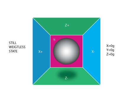
If we take this box in a place with no gravitation fields or for that matter with no other fields that might affect the ball's position – the ball will simply float in the middle of the box. You can imagine the box is in outer-space far-far away from any cosmic bodies, or if such a place is hard to find imagine at least a space craft orbiting around the planet where everything is in weightless state . From the picture above you can see that we assign to each axis a pair of walls (we removed the wall Y+ so we can look inside the box). Imagine that each wall is pressure sensitive. If we move suddenly the box to the left (we accelerate it with acceleration 1g = 9.8m/s^2), the ball will hit the wall X-. We then measure the pressure force that the ball applies to the wall and output a value of -1g on the X axis.
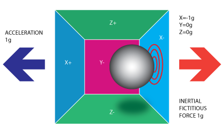
Please note that the accelerometer will actually detect a force that is directed in the opposite direction from the acceleration vector. This force is often called Inertial Force or Fictitious Force . One thing you should learn from this is that an accelerometer measures acceleration indirectly through a force that is applied to one of it's walls (according to our model, it might be a spring or something else in real life accelerometers). This force can be caused by the acceleration , but as we'll see in the next example it is not always caused by acceleration.
If we take our model and put it on Earth the ball will fall on the Z- wall and will apply a force of 1g on the bottom wall, as shown in the picture below:
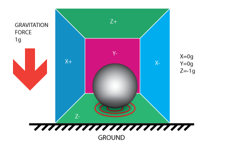
In this case the box isn't moving but we still get a reading of -1g on the Z axis. The pressure that the ball has applied on the wall was caused by a gravitation force. In theory it could be a different type of force – for example, if you imagine that our ball is metallic, placing a magnet next to the box could move the ball so it hits another wall. This was said just to prove that in essence accelerometer measures force not acceleration. It just happens that acceleration causes an inertial force that is captured by the force detection mechanism of the accelerometer.
While this model is not exactly how a MEMS sensor is constructed it is often useful in solving accelerometer related problems. There are actually similar sensors that have metallic balls inside, they are called tilt switches, however they are more primitive and usually they can only tell if the device is inclined within some range or not, not the extent of inclination.
So far we have analyzed the accelerometer output on a single axis and this is all you'll get with a single axis accelerometers. The real value of triaxial accelerometers comes from the fact that they can detect inertial forces on all three axes. Let's go back to our box model, and let's rotate the box 45 degrees to the right. The ball will touch 2 walls now: Z- and X- as shown in the picture below:
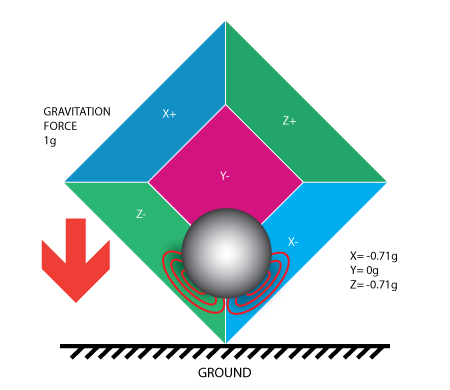
The values of 0.71 are not arbitrary, they are actually an approximation for SQRT(1/2). This will become more clear as we introduce our next model for the accelerometer.
In the previous model we have fixed the gravitation force and rotated our imaginary box. In last 2 examples we have analyzed the output in 2 different box positions, while the force vector remained constant. While this was useful in understanding how the accelerometer interacts with outside forces, it is more practical to perform calculations if we fix the coordinate system to the axes of the accelerometer and imagine that the force vector rotates around us.
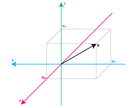
Please have a look at the model above, I preserved the colors of the axes so you can make a mental transition from the previous model to the new one. Just imagine that each axis in the new model is perpendicular to the respective faces of the box in the previous model. The vector R is the force vector that the accelerometer is measuring (it could be either the gravitation force or the inertial force from the examples above or a combination of both). Rx, Ry, Rz are projection of the R vector on the X,Y,Z axes. Please notice the following relation:
R^2 = Rx^2 + Ry^2 + Rz^2 (Eq. 1)
which is basically the equivalent of the Pythagorean theorem in 3D.
Remember that a little bit earlier I told you that the values of SQRT(1/2) ~ 0.71 are not random. If you plug them in the formula above, after recalling that our gravitation force was 1 g we can verify that:
1^2 = (-SQRT(1/2) )^2 + 0 ^2 + (-SQRT(1/2))^2
simply by substituting R=1, Rx = -SQRT(1/2), Ry = 0 , Rz = -SQRT(1/2) in Eq.1
After a long preamble of theory we're getting closer to real life accelerometers. The values Rx, Ry, Rz are actually linearly related to the values that your real-life accelerometer will output and that you can use for performing various calculations.
Before we get there let's talk a little about the way accelerometers will deliver this information to us. Most accelerometers will fall in two categories: digital and analog. Digital accelerometers will give you information using a serial protocol like I2C , SPI or USART, while analog accelerometers will output a voltage level within a predefined range that you have to convert to a digital value using an ADC (analog to digital converter) module. I will not go into much detail about how ADC works, partly because it is such an extensive topic and partly because it is different from one platform to another. Some microcontroller will have a built-in ADC modules some of them will need external components in order to perform the ADC conversions. No matter what type of ADC module you use you'll end up with a value in a certain range. For example a 10-bit ADC module will output a value in the range of 0..1023, note that 1023 = 2^10 -1. A 12-bit ADC module will output a value in the range of 0..4095, note that 4095 = 2^12-1.
Let's move on by considering a simple example, suppose our 10bit ADC module gave us the following values for the three accelerometer channels (axes):
AdcRx = 586
AdcRy = 630
AdcRz = 561
Each ADC module will have a reference voltage, let's assume in our example it is 3.3V. To convert a 10bit adc value to voltage we use the following formula:
VoltsRx = AdcRx * Vref / 1023
A quick note here: that for 8bit ADC the last divider would be 255 = 2 ^ 8 -1 , and for 12bit ADC last divider would be 4095 = 2^12 -1.
Applying this formula to all 3 channels we get:
VoltsRx = 586 * 3.3V / 1023 =~ 1.89V (we round all results to 2 decimal points)
VoltsRy = 630 * 3.3V / 1023 =~ 2.03V
VoltsRz = 561 * 3.3V / 1023 =~ 1.81V
Each accelerometer has a zero-g voltage level, you can find it in specs, this is the voltage that corresponds to 0g. To get a signed voltage value we need to calculate the shift from this level. Let's say our 0g voltage level is VzeroG = 1.65V. We calculate the voltage shifts from zero-g voltage as follows::
DeltaVoltsRx = 1.89V – 1.65V = 0.24V
DeltaVoltsRy = 2.03V – 1.65V = 0.38V
DeltaVoltsRz = 1.81V – 1.65V = 0.16V
We now have our accelerometer readings in Volts , it's still not in g (9.8 m/s^2), to do the final conversion we apply the accelerometer sensitivity, usually expressed in mV/g. Lets say our Sensitivity = 478.5mV/g = 0.4785V/g. Sensitivity values can be found in accelerometer specifications. To get the final force values expressed in g we use the following formula:
Rx = DeltaVoltsRx / Sensitivity
Rx = 0.24V / 0.4785V/g =~ 0.5g
Ry = 0.38V / 0.4785V/g =~ 0.79g
Rz = 0.16V / 0.4785V/g =~ 0.33g
We could of course combine all steps in one formula, but I went through all the steps to make it clear how you go from ADC readings to a force vector component expressed in g.
Rx = (AdcRx * Vref / 1023 – VzeroG) / Sensitivity (Eq.2)
Ry = (AdcRy * Vref / 1023 – VzeroG) / Sensitivity
Rz = (AdcRz * Vref / 1023 – VzeroG) / Sensitivity
We now have all 3 components that define our inertial force vector, if the device is not subject to other forces other than gravitation, we can assume this is the direction of our gravitation force vector. If you want to calculate inclination of device relative to the ground you can calculate the angle between this vector and Z axis. If you are also interested in per-axis direction of inclination you can split this result into 2 components: inclination on the X and Y axis that can be calculated as the angle between gravitation vector and X / Y axes. Calculating these angles is more simple than you might think, now that we have calculated the values for Rx,Ry and Rz. Let's go back to our last accelerometer model and do some additional notations:
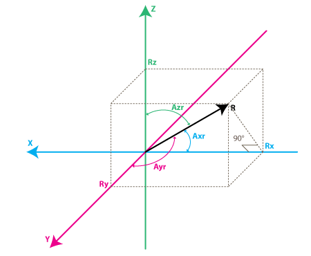
The angles that we are interested in are the angles between X,Y,Z axes and the force vector R. We'll define these angles as Axr, Ayr, Azr. You can notice from the right-angle triangle formed by R and Rx that:
cos(Axr) = Rx / R , and similarly :
cos(Ayr) = Ry / R
cos(Azr) = Rz / R
We can deduct from Eq.1 that R = SQRT( Rx^2 + Ry^2 + Rz^2).
We can find now our angles by using arccos() function (the inverse cos() function ):
Axr = arccos(Rx/R)
Ayr = arccos(Ry/R)
Azr = arccos(Rz/R)
We've gone a long way to explain the accelerometer model, just to come up to these formulas. Depending on your applications you might want to use any intermediate formulas that we have derived. We'll also introduce the gyroscope model soon, and we'll see how accelerometer and gyroscope data can be combined to provide even more accurate inclination estimations.
But before we do that let's do some more useful notations:
cosX = cos(Axr) = Rx / R
cosY = cos(Ayr) = Ry / R
cosZ = cos(Azr) = Rz / R
This triplet is often called Direction Cosine , and it basically represents the unit vector (vector with length 1) that has same direction as our R vector. You can easily verify that:
SQRT(cosX^2 + cosY^2 + cosZ^2) = 1
This is a nice property since it absolve us from monitoring the modulus(length) of R vector. Often times if we're just interested in direction of our inertial vector, it makes sense to normalize it's modulus in order to simplify other calculations.
Part 2. Gyroscope
We're not going to introduce any equivalent box model for the gyroscope like we did for accelerometer, instead we're going to jump straight to the second accelerometer model and we'll show what does the gyroscope measure according to this model.
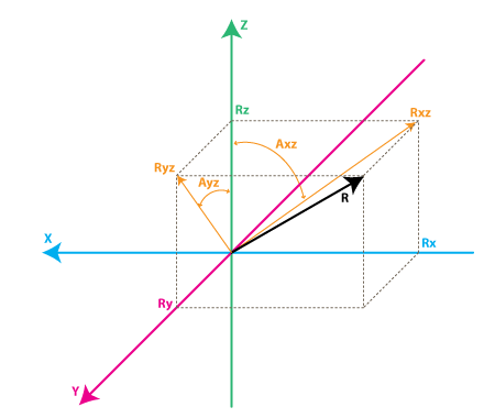
Each gyroscope channel measures the rotation around one of the axes. For instance a 2-axes gyroscope will measure the rotation around (or some may say "about") the X and Y axes. To express this rotation in numbers let's do some notations. First let's define:
Rxz – is the projection of the inertial force vector R on the XZ plane
Ryz – is the projection of the inertial force vector R on the YZ plane
From the right-angle triangle formed by Rxz and Rz, using Pythagorean theorem we get:
Rxz^2 = Rx^2 + Rz^2 , and similarly:
Ryz^2 = Ry^2 + Rz^2
also note that:
R^2 = Rxz^2 + Ry^2 , this can be derived from Eq.1 and above equations, or it can be derived from right-angle triangle formed by R and Ryz
R^2 = Ryz^2 + Rx^2
We're not going to use these formulas in this article but it is useful to note the relation between all the values in our model.
Instead we're going to define the angle between the Z axis and Rxz, Ryz vectors as follows:
Axz – is the angle between the Rxz (projection of R on XZ plane) and Z axis
Ayz – is the angle between the Ryz (projection of R on YZ plane) and Z axis
Now we're getting closer to what the gyroscope measures. Gyroscope measures the rate of changes of the angles defined above. In other words it will output a value that is linearly related to the rate of change of these angles. To explain this let's assume that we have measured the rotation angle around axis Y (that would be Axz angle) at time t0, and we define it as Axz0, next we measured this angle at a later time t1 and it was Axz1. The rate of change will be calculated as follows:
RateAxz = (Axz1 – Axz0) / (t1 – t0).
If we express Axz in degrees, and time in seconds , then this value will be expressed in deg/s . This is what a gyroscope measures.
In practice a gyroscope(unless it is a special digital gyroscope) will rarely give you a value expressed in deg/s. Same as for accelerometer you'll get an ADC value that you'll need to convert to deg/s using a formula similar to Eq. 2 that we have defined for accelerometer. Let's introduce the ADC to deg/s conversion formula for gyroscope (we assume we're using a 10bit ADC module , for 8bit ADC replace 1023 with 255, for 12bit ADC replace 1023 with 4095).
RateAxz = (AdcGyroXZ * Vref / 1023 – VzeroRate) / Sensitivity Eq.3
RateAyz = (AdcGyroYZ * Vref / 1023 – VzeroRate) / Sensitivity
AdcGyroXZ, AdcGyroYZ – are obtained from our adc module and they represent the channels that measure the rotation of projection of R vector in XZ respectively in YZ planes, which is the equivalent to saying rotation was done around Y and X axes respectively.
Vref – is the ADC reference voltage we'll use 3.3V in the example below
VzeroRate – is the zero-rate voltage, in other words the voltage that the gyroscope outputs when it is not subject to any rotation, for the Acc_Gyro board it is for example 1.23V (you can find this values in the specs – but don't trust the specs most gyros will suffer slight offset after being soldered so measure VzeroRate for each axis output using a voltmeter, usually this value will not change over time once the gyro was soldered, if it variates – write a calibration routine to measure it before device start-up, user must be instructed to keep device in still position upon start-up for gyros to calibrate).
Sensitivity – is the sensitivity of your gyroscope it is expressed in mV / (deg / s) often written as mV/deg/s , it basically tells you how many mV will the gyroscope output increase , if you increase the rotation speed by one deg/s. The sensitivity of Acc_Gyro board is for example 2mV/deg/s or 0.002V/deg/s
Let's take an example, suppose our ADC module returned following values:
AdcGyroXZ = 571
AdcGyroXZ = 323
Using the above formula, and using the specs parameters of Acc_Gyro board we'll get:
RateAxz = (571 * 3.3V / 1023 – 1.23V) / ( 0.002V/deg/s) =~ 306 deg/s
RateAyz = (323 * 3.3V / 1023 – 1.23V) / ( 0.002V/deg/s) =~ -94 deg/s
In other words the device rotates around the Y axis (or we can say it rotates in XZ plane) with a speed of 306 deg/s and around the X axis (or we can say it rotates in YZ plane) with a speed of -94 deg/s. Please note that the negative sign means that the device rotates in the opposite direction from the conventional positive direction. By convention one direction of rotation is positive. A good gyroscope specification sheet will show you which direction is positive, otherwise you'll have to find it by experimenting with the device and noting which direction of rotation results in increasing voltage on the output pin. This is best done using an oscilloscope since as soon as you stop the rotation the voltage will drop back to the zero-rate level. If you're using a multimeter you'd have to maintain a constant rotation rate for at least few seconds and note the voltage during this rotation, then compare it with the zero-rate voltage. If it is greater than the zero-rate voltage it means that direction of rotation is positive.
Part 3. Putting it all together. Combining accelerometer and gyroscope data.
If you're reading this article you probably acquired or are planning to acquire a IMU device, or probably you're planning to build one from separate accelerometer and gyroscope devices.
NOTE: FOR PRACTICAL IMPLEMENTATION AND TESTING OF THIS ALGORITHM PLEASE READ THIS ARTICLE:
http://starlino.com/imu_kalman_arduino.html
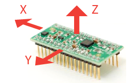
The first step in using a combination IMU device that combines an accelerometer and a gyroscope is to align their coordinate systems. The easiest way to do it is to choose the coordinate system of accelerometer as your reference coordinate system. Most accelerometer data sheets will display the direction of X,Y,Z axes relative to the image of the physical chip or device. For example here are the directions of X,Y,Z axes as shown in specifications for the Acc_Gyro board:
Next steps are:
– identify the gyroscope outputs that correspond to RateAxz , RateAyz values discussed above.
– determine if these outputs need to be inverted due to physical position of gyroscope relative to the accelerometer
Do not assume that if a gyroscope has an output marked X or Y, it will correspond to any axis in the accelerometer coordinate system, even if this output is part of an IMU unit. The best way is to test it.
Here is a sample sequence to determine which output of gyroscope corresponds to RateAxz value discussed above.
– start from placing the device in horizontal position. Both X and Y outputs of accelerometer would output the zero-g voltage (for example for Acc_Gyro board this is 1.65V)
– next start rotating the device around the Y axis, another way to say it is that you rotate the device in XZ plane, so that X and Z accelerometer outputs change and Y output remains constant.
– while rotating the device at a constant speed note which gyroscope output changes, the other gyroscope outputs should remain constant
– the gyroscope output that changed during the rotation around Y axis (rotation in XZ plane) will provide the input value for AdcGyroXZ, from which we calculate RateAxz
– the final step is to ensure the rotation direction corresponds to our model, in some cases you may have to invert the RateAxz value due to physical position of gyroscope relative to the accelerometer
– perform again the above test, rotating the device around the Y axis, this time monitor the X output of accelerometer (AdcRx in our model). If AdcRx grows (the first 90 degrees of rotation from horizontal position), then AdcGyroXZ should decrease. This is due to the fact that we are monitoring the gravitation vector and when device rotates in one direction the vector will rotate in oposite direction (relative to the device coordonate system, which we are using). So, otherwise you need to invert RateAxz , you can achieve this by introducing a sign factor in Eq.3, as follows:
RateAxz = InvertAxz * (AdcGyroXZ * Vref / 1023 – VzeroRate) / Sensitivity , where InvertAxz is 1 or -1
same test can be done for RateAyz , by rotating the device around the X axis, and you can identify which gyroscope output corresponds to RateAyz, and if it needs to be inverted. Once you have the value for InvertAyz, you should use the following formula to calculate RateAyz:
RateAyz = InvertAyz * (AdcGyroYZ * Vref / 1023 – VzeroRate) / Sensitivity
If you would do these tests on Acc_Gyro board you would get following results:
– the output pin for RateAxz is GX4 and InvertAxz = 1
– the output pin for RateAyz is GY4 and InvertAyz = 1
From this point on we'll consider that you have setup your IMU in such a way that you can calculate correct values for Axr, Ayr, Azr (as defined Part 1. Accelerometer) and RateAxz, RateAyz (as defined in Part 2. Gyroscope). Next we'll analyze the relations between these values that turn out useful in obtaining more accurate estimation of the inclination of the device relative to the ground plane.
You might be asking yourself by this point, if accelerometer model already gave us inclination angles of Axr,Ayr,Azr why would we want to bother with the gyroscope data ? The answer is simple: accelerometer data can't always be trusted 100%. There are several reason, remember that accelerometer measures inertial force, such a force can be caused by gravitation (and ideally only by gravitation), but it might also be caused by acceleration (movement) of the device. As a result even if accelerometer is in a relatively stable state, it is still very sensitive to vibration and mechanical noise in general. This is the main reason why most IMU systems use a gyroscope to smooth out any accelerometer errors. But how is this done ? And is the gyroscope free from noise ?
The gyroscope is not free from noise however because it measures rotation it is less sensitive to linear mechanical movements, the type of noise that accelerometer suffers from, however gyroscopes have other types of problems like for example drift (not coming back to zero-rate value when rotation stops). Nevertheless by averaging data that comes from accelerometer and gyroscope we can obtain a relatively better estimate of current device inclination than we would obtain by using the accelerometer data alone.
In the next steps I will introduce an algorithm that was inspired by some ideas used in Kalman filter, however it is by far more simple and easier to implement on embedded devices. Before that let's see first what we want our algorithm to calculate. Well , it is the direction of gravitation force vector R = [Rx,Ry,Rz] from which we can derive other values like Axr,Ayr,Azr or cosX,cosY,cosZ that will give us an idea about the inclination of our device relative to the ground plane, we discuss the relation between these values in Part 1. One might say – don't we already have these values Rx, Ry , Rz from Eq.2 in Part 1 ? Well yes, but remember that these values are derived from accelerometer data only, so if you would be to use them directly in your application you might get more noise than your application can tolerate. To avoid further confusion let's re-define the accelerometer measurements as follows:
Racc – is the inertial force vector as measured by accelerometer, that consists of following components (projections on X,Y,Z axes):
RxAcc = (AdcRx * Vref / 1023 – VzeroG) / Sensitivity
RyAcc = (AdcRy * Vref / 1023 – VzeroG) / Sensitivity
RzAcc = (AdcRz * Vref / 1023 – VzeroG) / Sensitivity
So far we have a set of measured values that we can obtain purely from accelerometer ADC values. We'll call this set of data a "vector" and we'll use the following notation.
Racc = [RxAcc,RyAcc,RzAcc]
Because these components of Racc can be obtained from accelerometer data , we can consider it an input to our algorithm.
Please note that because Racc measures the gravitation force you'll be correct if you assume that the length of this vector defined as follows is equal or close to 1g.
|Racc| = SQRT(RxAcc^2 +RyAcc^2 + RzAcc^2),
However to be sure it makes sense to update this vector as follows:
Racc(normalized) = [RxAcc/|Racc| , RyAcc/|Racc| , RzAcc/|Racc|].
This will ensure the length of your normalized Racc vector is always 1.
Next we'll introduce a new vector and we'll call it
Rest = [RxEst,RyEst,RzEst]
This will be the output of our algorithm , these are corrected values based on gyroscope data and based on past estimated data.
Here is what our algorithm will do:
– accelerometer tells us: "You are now at position Racc"
– we say "Thank you, but let me check",
– then correct this information with gyroscope data as well as with past Rest data and we output a new estimated vector Rest.
– we consider Rest to be our "best bet" as to the current position of the device.
Let's see how we can make it work.
We'll start our sequence by trusting our accelerometer and assigning:
Rest(0) = Racc(0)
By the way remember Rest and Racc are vectors , so the above equation is just a simple way to write 3 sets of equations, and avoid repetition:
RxEst(0) = RxAcc(0)
RyEst(0) = RyAcc(0)
RzEst(0) = RzAcc(0)
Next we'll do regular measurements at equal time intervals of T seconds, and we'll obtain new measurements that we'll define as Racc(1), Racc(2) , Racc(3) and so on. We'll also issue new estimates at each time intervals Rest(1), Rest(2), Rest(3) and so on.
Suppose we're at step n. We have two known sets of values that we'd like to use:
Rest(n-1) – our previous estimate, with Rest(0) = Racc(0)
Racc(n) – our current accelerometer measurement
Before we can calculate Rest(n) , let's introduce a new measured value, that we can obtain from our gyroscope and a previous estimate.
We'll call it Rgyro , and it is also a vector consisting of 3 components:
Rgyro = [RxGyro,RyGyro,RzGyro]
We'll calculate this vector one component at a time. We'll start with RxGyro.
Let's start by observing the following relation in our gyroscope model, from the right-angle triangle formed by Rz and Rxz we can derive that:
tan(Axz) = Rx/Rz => Axz = atan2(Rx,Rz)
Atan2 might be a function you never used before, it is similar to atan, except it returns values in range of (-PI,PI) as opposed to (-PI/2,PI/2) as returned by atan, and it takes 2 arguments instead of one. It allows us to convert the two values of Rx,Rz to angles in the full range of 360 degrees (-PI to PI). You can read more about atan2 here.
So knowing RxEst(n-1) , and RzEst(n-1) we can find:
Axz(n-1) = atan2( RxEst(n-1) , RzEst(n-1) ).
Remember that gyroscope measures the rate of change of the Axz angle. So we can estimate the new angle Axz(n) as follows:
Axz(n) = Axz(n-1) + RateAxz(n) * T
Remember that RateAxz can be obtained from our gyroscope ADC readings. A more precise formula can use an average rotation rate calculated as follows:
RateAxzAvg = ( RateAxz(n) + RateAxz(n-1) ) / 2
Axz(n) = Axz(n-1) + RateAxzAvg * T
The same way we can find:
Ayz(n) = Ayz(n-1) + RateAyz(n) * T
Ok so now we have Axz(n) and Ayz(n). Where do we go from here to deduct RxGyro/RyGyro ? From Eq. 1 we can write the length of vector Rgyro as follows:
|Rgyro| = SQRT(RxGyro^2 + RyGyro^2 + RzGyro^2)
Also because we normalized our Racc vector, we may assume that it's length is 1 and it hasn't changed after the rotation, so it is relatively safe to write:
|Rgyro| = 1
Let's adopt a temporary shorter notation for the calculations below:
x =RxGyro , y=RyGyro, z=RzGyro
Using the relations above we can write:
x = x / 1 = x / SQRT(x^2+y^2+z^2)
Let's divide numerator and denominator of fraction by SQRT(x^2 + z^2)
x = ( x / SQRT(x^2 + z^2) ) / SQRT( (x^2 + y^2 + z^2) / (x^2 + z^2) )
Note that x / SQRT(x^2 + z^2) = sin(Axz), so:
x = sin(Axz) / SQRT (1 + y^2 / (x^2 + z^2) )
Now multiply numerator and denominator of fraction inside SQRT by z^2
x = sin(Axz) / SQRT (1 + y^2 * z ^2 / (z^2 * (x^2 + z^2)) )
Note that z / SQRT(x^2 + z^2) = cos(Axz) and y / z = tan(Ayz), so finally:
x = sin(Axz) / SQRT (1 + cos(Axz)^2 * tan(Ayz)^2 )
Going back to our notation we get:
RxGyro = sin(Axz(n)) / SQRT (1 + cos(Axz(n))^2 * tan(Ayz(n))^2 )
same way we find that
RyGyro = sin(Ayz(n)) / SQRT (1 + cos(Ayz(n))^2 * tan(Axz(n))^2 )
Side Note: it is possible to further simplify this formula. By dividing both parts of the fraction by sin(Axz(n)) you get:
RxGyro = 1 / SQRT (1/ sin(Axz(n))^2 + cos(Axz(n))^2 / sin(Axz(n))^2 * tan(Ayz(n))^2 )
RxGyro = 1 / SQRT (1/ sin(Axz(n))^2 + cot(Axz(n))^2 * sin(Ayz(n))^2 / cos(Ayz(n))^2 )
now add and substract cos(Axz(n))^2/sin(Axz(n))^2 = cot(Axz(n))^2
RxGyro = 1 / SQRT (1/ sin(Axz(n))^2 – cos(Axz(n))^2/sin(Axz(n))^2 + cot(Axz(n))^2 * sin(Ayz(n))^2 / cos(Ayz(n))^2 + cot(Axz(n))^2 )
and by grouping terms 1&2 and then 3&4 we get
RxGyro = 1 / SQRT (1 + cot(Axz(n))^2 * sec(Ayz(n))^2 ), where cot(x) = 1 / tan(x) and sec(x) = 1 / cos(x)
This formula uses only 2 trigonometric functions and can be computationally less expensive. If you have Mathematica program you can verify it
by evaluating FullSimplify [Sin[A]^2/ ( 1 + Cos[A]^2 * Tan[B]^2)]
Now, finally we can find:
RzGyro = Sign(RzGyro)*SQRT(1 – RxGyro^2 – RyGyro^2).
Where Sign(RzGyro) = 1 when RzGyro>=0 , and Sign(RzGyro) = -1 when RzGyro<0.
One simple way to estimate this is to take:
Sign(RzGyro) = Sign(RzEst(n-1))
In practice be careful when RzEst(n-1) is close to 0. You may skip the gyro phase altogether in this case and assign: Rgyro = Rest(n-1). Rz is used as a reference for calculating Axz and Ayz angles and when it's close to 0, values may overflow and trigger bad results. You'll be in domain of large floating point numbers where tan() / atan() function implementations may lack precision.
So let's recap what we have so far, we are at step n of our algorithm and we have calculated the following values:
Racc – current readings from our accelerometer
Rgyro – obtained from Rest(n-1) and current gyroscope readings
Which values do we use to calculate the updated estimate Rest(n) ? You probably guessed that we'll use both. We'll use a weighted average, so that:
Rest(n) = (Racc * w1 + Rgyro * w2 ) / (w1 + w2)
We can simplify this formula by dividing both numerator and denominator of the fraction by w1.
Rest(n) = (Racc * w1/w1 + Rgyro * w2/w1 ) / (w1/w1 + w2/w1)
and after substituting w2/w1 = wGyro we get:
Rest(n) = (Racc + Rgyro * wGyro ) / (1 + wGyro)
In the above formula wGyro tells us how much we trust our gyro compared to our accelerometer. This value can be chosen experimentally usually values between 5..20 will trigger good results.
The main difference of this algorithm from Kalman filter is that this weight is relatively fixed , whereas in Kalman filter the weights are permanently updated based on the measured noise of the accelerometer readings. Kalman filter is focused at giving you "the best" theoretical results, whereas this algorithm can give you results "good enough" for your practical application. You can implement an algorithm that adjusts wGyro depending on some noise factors that you measure, but fixed values will work well for most applications.
We are one step away from getting our updated estimated values:
RxEst(n) = (RxAcc + RxGyro * wGyro ) / (1 + wGyro)
RyEst(n) = (RyAcc + RyGyro * wGyro ) / (1 + wGyro)
RzEst(n) = (RzAcc + RzGyro * wGyro ) / (1 + wGyro)
Now let's normalize this vector again:
R = SQRT(RxEst(n) ^2 + RyEst(n)^2 + RzEst(n)^2 )
RxEst(n) = RxEst(n)/R
RyEst(n) = RyEst(n)/R
RzEst(n) = RzEst(n)/R
And we're ready to repeat our loop again.
NOTE: FOR PRACTICAL IMPLEMENTATION AND TESTING OF THIS ALGORITHM PLEASE READ THIS ARTICLE:
http://starlino.com/imu_kalman_arduino.html
Other Resources on Accelerometer and Gyroscope IMU Fusion:
http://www.mikroquad.com/pub/Research/ComplementaryFilter/filter.pdf
http://stackoverflow.com/questions/1586658/combine-gyroscope-and-accelerometer-data
http://www.dimensionengineering.com/accelerometers.htm
//starlino//
Your tutorial is helpful, but some of the equations are quite confusing, as I am more of expecting so what is now the formula to get the mixed output of the accelerometer and the gyroscope?
I will be using a single axis gyro and accelerometer. So if ever I’ll take one of your formulas, say RxEst(n) = (RxAcc + RxGyro * wGyro ) / (1 + wGyro);
and from my understanding from your tutorial,
RxAcc – ADC reading of the acclerometer
RxGyro – is the previous reading of the Gyro, so it means, RXGyro(n-1), as n is the current.
So does this mean that RxGyro is a direct ADC reading from the gyroscope or is there a mathematical computation still needed to get the value of RxGyro?
Thank you.
Sometimes it helps to go back in the text and follow where a specific variable came from. I also recommend having a look at the Arduino implementation of this algorithm it’s only a page of code so you might start there and then come back here for details:
Now let’s go back to the “confusing” formula.
RxEst(n) = (RxAcc + RxGyro * wGyro ) / (1 + wGyro);
RxAcc is a value between -1..1 and it is derived from accelerometer ADC reading:
RxAcc = (AdcRx * Vref / 1023 – VzeroG) / Sensitivity
Next RxGyro is derived from RxEst(n-1) and RzEst(n-1) and current (or average of current and previous) Gyro reading ,there are some intermediary variables used:
RateAxz = InvertAxz * (AdcGyroXZ * Vref / 1023 – VzeroRate) / Sensitivity
Axz(n-1) = atan2( RxEst(n-1) , RzEst(n-1) )
Ayz(n-1) = atan2( RyEst(n-1) , RzEst(n-1) )
Axz(n) = Axz(n-1) + RateAxz(n) * T
Ayz(n) = Ayz(n-1) + RateAyz(n) * T
RxGyro = sin(Axz(n)) / SQRT (1 + cos(Axz(n))^2 * tan(Ayz(n))^2 )
Because you’re using a single-axis accelerometer and gyro (it might be a self-balancing robot you’re building), I’m assuming you have little rotation on Y axis, so you
will use:
RyAcc = RyGyro = RyEst = 0 , in all formulas
you can also deduct:
RzAcc = SQRT( 1 – RxAcc*RxAcc)
RzGyro = SQRT( 1 – RxGyro*RxGyro)
RzEst = SQRT( 1 – RxEst*RxEst)
Also you would have to observe sign for RzAcc,RzGyro,RzEst, but you can choose such a coordinate system for your balancing robot, so that sign of Z axis does not change, well unless your bot flips over upside down.
You’ll see that for your case formula will become more simple, in particular notice that
Ayz(n), Ayz(n-1) will become 0 , since there’s no rotation in the YZ plane so RateAyz(n) = 0.
I’ll leave the reduction of formula to you, you may share the results with others , so let me know the results !
Thank you for the reply, I’ll do te reduction formulas and post it here for you to comment. Thank you for the reply, yes sir, you are correct, I am trying to build a self balancing robot.
May I also clarify, if the output RxEst(n) will be the input now to my PID controller?
Thank you again.
For a self balancing bot I would choose Z axis pointing straight up(or down) so it’s sign is constant (assuming your bot will never rotate more than 180 degrees).
RxEst will be sin(Alpha). Where Alpha is the angled formed by Z axis (pointing up) and the vertical axis of the robot.
In balance position you would want RxEst to be close to 0.
You can feed either RxEst to your feedback loop, or arcsin(RxEst) = Alpha, it doesn’t really matter since for small angles they are close anyways.
Your main challenge will be updating the PWM signal to the motors fast enough so that the bot does not flip over. Forget about servo motors since those you can update only once every 20ms or so.
You’ll need to do a lot of tuning and monitoring, this is crucial , for that matter have a look at the SerialChart software.
http://code.google.com/p/serialchart/
RxGyro = sin(Axz(n)) / SQRT (1 + cos(Axz(n))^2 * tan(Ayz(n))^2 )
To get RxGyro at single axis.
Ayz(n) = 0;
therefore:
RxGYro = sin(Axz(n)) as tan(0) = 0; does sin(Axz(n)) is in deg or radians?
Axz(n) = [ADCGyro*Vref/1023]/Sensitivity ; may I ask what is the need of the invert Axz?
I will be using a PIC micro and maximize its 10 bit capability, so the input range is 0 to 1023, my center or 0 deg will give an ADC value of 0 as my code in C is ADC_Value – 512.
ADXRS300 gives an output of 2.5 at 0deg/s.
In C implementation, to avoid unnecessary conversion, I think to get the tilt of accelerometer it will be better to just stick with ADCRx – 512 (using 10 bit adc) to get the angle, at 3.3V input at the accelerometer, the typical 0deg position will be 1.65 which will yield also 512 in a 3.3V vref, a greater than 512 value means tilt angle at the 1st quadrant then a less than 512 adc reading will means an angle tilt in the 2nd quadrant.
The formula “Rx = (AdcRx * Vref / 1023 – VzeroG) / Sensitivity” will yield output in g’s which has the highest value of 1 or -1 at the opposite direction.
In the said example: AdcRx = 586
It will be 586 – 512 = 74; 74 is the RAW TILT ANGLE DATA, to convert it to degrees, one must use the formula
Vout = 586 * 3.3V / 1023
Vout = Voffset + sensitivity*sin(angle)
Therefore for the Gyro as the Gyro data is RxGYro = sin(Axz(n)) and xz(n) = [ADCGyro*Vref/1023]/Sensitivity;
so RxGyro RAW DATA = Rxyro ADC – 512;
– please correct if my analysis is wrong. Thanks.
Is my analysis right?
Yes you can express the zero-point in ADC values (512 in your case). However at some point you’ll need to add the gyro update to the angle, so make sure you add “apples” to “apples”.
I would suggest the following for your case where
RyAcc = 0 => Rxz = 1 (projection of R on XZ plane), therefore:
Axz = arcsin(RxAcc)
Start loop assuming AxEst = Axz,
Then loop through the following:
Add the RateAxz (from gyro adc reading), and get
AxzGyro = AxzEst + RateAxz * T
Next you can apply the weighted average directly to angle values
AxzEst = ( AxzAcc + wGyro * AxzGyro ) / (1 + wGyro ).
Repeat loop.
You would use Axz inside the loop as an input to your PID control function. It represents the angle between the robot’s vertical axis, and the fixed Z axis that is perpendicular to the ground plane.
In this formula from the statement
Atan2 might be a function you never used before, it is similar to atan, except it returns values in range of (-PI,PI) as opposed to (-PI/2,PI/2) as returned by atan, and it takes 2 arguments instead of one. It allows us to convert the two values of Rx,Rz to angles in the full range of 360 degrees (-PI to PI). You can read more about atan2 here.
So knowing RxEst(n-1) , and RzEst(n-1) we can find:
Axz(n-1) = atan2( RxEst(n-1) , RzEst(n-1) ).
Axz(n) = Axz(n-1) + RateAxz(n) * T
————
Just would like to clarify that,
RxEst(n-1) , RzEst(n-1) are the position of the accelerometers from the previous reading.
Axz(n-1) is the angle between RxEst(n-1) , RzEst(n-1)
RateAxz(n) * T is the reading from gyroscope, unit can be deg/sec or deg per second then multiplied by time to get the deg, or angle traveled by the gyroscope.
T is the sampling period, say for sampling freq of 500Hz, T will be 2ms
———–
Please correct me again if I am wrong, if basing from datasheets of the gyro and accelerometer, the ouputs were, for gyro is in mv/deg/sec, and accelerometer is mv/deg.
If I will not use any ADC data to voltage conversion and voltage conversion to deg or deg/s, I guess we can assume that the raw 10bit adc data can already give us the position or average angle of the accelerometer,
so the avarage data basing from the formula, this is raw data from ADC.
AxzEst = ( AxzAcc + wGyro * AxzGyro ) / (1 + wGyro ).
AxzEst[ADC RAW Data](n) = (AxzAcc[ADC Raw Data](n) *wGyro*AxzGyro[ADC Raw Data](n))/(1 + wGyro)
where AzxGyro[ADC Raw Data](n) = (AxzEst[ADC RAW Data](n-1) + AzxGyro[ADC Raw Data](n)*T) where T is the sampling frequency
This formula if correct is the simplified version, means this will be using raw data directly of the ADC readings, for display in the SerialChart software, and assumes the ADC data 512 means it is 0 deg.
Btw, why is it that the previous estimated position “AxzEst[ADC RAW Data](n-1)” be added to AzxGyro[ADC Raw Data](n)*T as stated in AxzGyro = AxzEst + RateAxz * T, be used as the AzxGyro[ADC Raw Data](n) or AxzGyro?
Thanks.
Some corrections:
>Axz(n-1) is the angle between RxEst(n-1) , RzEst(n-1)
Not exactly, the Rx and Rz are always at 90 degrees since they are projections of R on the X and Z axes. Axz is the angle between the Rxz (projection of R on XZ plane) and Z axis.
>AxzEst[ADC RAW Data](n) = (AxzAcc[ADC Raw Data](n) *wGyro*AxzGyro[ADC Raw Data](n))/(1 + wGyro)
I think there’s a typo, it should be
… AxzAcc[ADC Raw Data](n) + wGyro ….
>Btw, why is it that the previous estimated position “AxzEst[ADC RAW Data](n-1)” be added >to AzxGyro[ADC Raw Data](n)*T as stated in AxzGyro = AxzEst + RateAxz * T, be used as >the AzxGyro[ADC Raw Data](n) or AxzGyro?
Because AxzEst is the best estimate at the moment (it stores data from all last steps). If we would be using AxzAcc we would be simply discarding all that information.
Thank you for the reply, I had printed this site so I can read the whole article. I am doing now some calculations based from the actual devices I will be using. Tomorrow I wil post it here so you can correct it and other also can check it if it is ok.
Hi,
The value you will get, what will it be? I tried to follow the instructions and I thought I would have an angle in degrees/radians. Am I on the right track?
Regards
Jesmond
Thanks , 100000000 thanks, this is very helpful ,it’s really wonderful to read this simple tutorial about how to get the g unit from the analog. I really appreciate that, in spit of the correction in the comment .
Pingback: WWW.Analyst-TW.com » Pic based quad controller
sir i am using the sparkfun 5 dof breakout board and i plan to apply it on a self balancing robot. any suggestions on what experiment should i make to find wgyro? thank you very much
hi. im trying to build a self balancing robot. can you give me any tips on how i can experimentally find the value of wgyro? thank you very much
A value of 20-50 would work good for most cases. The greater the value the greater the smoothness of the curve.
If you increase it too much you’ll start to see delayed response to inclination.
Thank you for make a clear and simple implement of Kalman :)
I am using an three axis Gyro and Accelerometer IMU to implement Kalman filter.
How do I to add Gyro RateAxy in this implement ?
Because I want to implement rotate around Z axis.
Thanks,
Chien , you’ll need a magnetometer for sensing absolute position around Z axis , because an accelerometer cannot sense it. The rest of the calculations would be similar magnetometer points to North, while accelerometer points down to the ground.
Hi,
I need just one axis for my robot monitoring. For just one axis measurement, do I need a 3 axis accelerometer and just one axis gyro?
Regards!
Hi,
I need just one axis for my robot monitoring. For that do I need a 3 axis accelerometer and one axis gyro?
Regards!
Thanks for your answer.
sir i have two questions:
1. just to satisfy my curiosity and to be able to apply your method on different applications, how did you find wgyro?
2. and to clarify things, using this 5 dof the TILT with respect to the axes right: [RxGyro,RyGyro,RzGyro] for the accelerometer RxAcc,RyAcc,RzAcc right? but then you mentioned that the RzGyro has a Sign. is it correct that i should just use Rgyro = Rest(n-1) only when RzEst(n-1) is between (0,1)?
thank you very much
ineedkalman :
1. wgyro was determined experimentally I simply charted RxAcc and RxEst while simulating the type of movement the application will have . Slowly increased wgyro you reach the best satisfying point keeping 2 things in mind: if wgyro is too low then the noise is not eliminated, if wgyro is too high then you get a delayed RxEst compared to RxAcc and also you’ll notice a drift since wgyro is in fact the weight of moving average as well as the weight of integrating the gyro rate over time.
Another interesting approach especially if your project would be subject to extreme accelerations , is to weight wgyro based on how off it is from 1g value (it should be 1g if no external acceleration is present). If we have external acceleration, then we should increase the wgyro (we trust more our gyro than our accelerometer at that moment). Here is an example of similar usage in arduimu code, from DCM.pde file:
// Calculate the magnitude of the accelerometer vector
Accel_magnitude = sqrt(Accel_Vector[0]*Accel_Vector[0] + Accel_Vector[1]*Accel_Vector[1] + Accel_Vector[2]*Accel_Vector[2]);
Accel_magnitude = Accel_magnitude / GRAVITY; // Scale to gravity.
// Dynamic weighting of accelerometer info (reliability filter)
// Weight for accelerometer info (<0.5G = 0.0, 1G = 1.0 , >1.5G = 0.0)
Accel_weight = constrain(1 – 2*abs(1 – Accel_magnitude),0,1); //
2. As far as your second question I am not sure I understand it completely. The text mentioned that you should be careful when RzEst(n-1) is close to 0 , because tangent will tend to infinite and the floating numbers are not accurate in that region . You should simply use the RxAcc results. In the example Arduino code (see the other article), this is treated as follows:
//evaluate RwGyro vector
if(abs(RwEst[2]) < 0.1){ //Rz is too small and because it is used as reference for computing Axz, Ayz it's error fluctuations will amplify leading to bad results //in this case skip the gyro data and just use previous estimate for(w=0;w<=2;w++) RwGyro[w] = RwEst[w]; }else{ ..... Becase RzEst is calculated using the square root , you are loosing the sign , so you can just restore the sign from RzAcc , for example. Thus the algorithm can estimate RzEst from -1 to 1 (full range).
How do you eliminate the drift from the gyros, I mean, can you eliminate with this simple kalman filter de drift from the Gyros?
Gyro drift is compensating by the following:
1) first calibrate gyro upon startup to determine output Voltage while no motion is applied (see for example code for http://www.starlino.com/quadcopter_acc_gyro.html > imu.h > function() gyro_calibrate() )
2) while the device is in motion the gyro is compensated by the accelerometer influence, since the results from both sensors are fused with a weighted average wGyro
thank you very much for your patience and generosity in replying to my questions. on a separate note sir, i would like to inquire (1) if the readings from my accelerometer is erroneous or not. i get a stationary reading of 715 on a 10bit adc. the no load voltage specified on the data sheet is 1.65 v max, similar to yours. if i apply your calculations on a 3.3v reference then the voltage reading would be .65 v.
(2) im planning on implementing your tilt sensing mechanism on a wheeled robot meant for uneven roads. the robot’s speed is controlled via PID which lends itself to having movements that tend to be “jerky”. since the accelerometer is susceptible to vibrations, would this “jerky” characteristic be a hindrance (produce large tilt readings during jerks)?
thank you very much
(1) ineedkalman, check the output of your accelerometer with a voltmeter. What is the sensibility of your accelerometer and what axis are you measuring and what is the position of device during measurment , are you expexting a reading that corresponds to 0g or 1g ?
(2) for self balancing bot you need to use a gyro , if you fuse the data of both devices you will compensate for accelerometer “jerky” behavior, this is the whole idea why the fusion algorithm has to be used in some applications. You will also need to make wGyro dynamic (make it bigger when accelerometer vector magnitude deviates from 1 , and make it smaller when it is close to 1)
Hi, I am implementing your algorithm in c# and by outputting the results on SerialChart, I can see how it works.
I set wgyro to be 33 and see it went crazy when I tilted my IMU and then settled down at the angle i stopped at. Is it something that is expected? If not, what should I do to fix it?
well, I run a debug on the code and and found that the calculation of RwGyro is totally off (x ~= 0.9 at stationary position)!
So I guess my Gyro reading is off?
Yonghan Ching most likely your gyro offset is dragging the value, you need to find out VzeroRate (for each axis it’s slightly different !) experimentally , not just take it from specs .
well… looks like I did the time conversions incorrectly… dumb me… now it’s working perfectly using Wgyro = 8.5!
Video here: http://www.youtube.com/watch?v=ry75OpNrsoM
I am trying to use this method to get position with data from a 3 axis gyro and 3 axis accelerometer, but I am not seeing the output that I expect. The readings from my accelerometer when idle are (0, 0, 1), 1g downward which is of course gravity. When I input those values and assume no rotation, the projected movement is 1 unit downward. I was under the impression that this method would account for the force of gravity, so when the accelerometer was idle for example, it would estimate the movement to be zero in all directions. Did I misunderstand something or am I perhaps doing my math wrong?
Kols, are you talking about position or inclination, this article only describes the inclination calculation. To get position in 3d space with an accelerometer you would have to integrate values once to get speed and then twice to get position , you will get huge errors, but you can use same idea of complimentary filter to correct the position from time to time using a more coarse sensor like for example a GPS, for an enclosed space you can use triangulation with some beacon signals.
I was talking about position. That makes the outputs make more sense now. Am I more or less stuck using ‘suvat’ equations then for a [very] rough position then?
Pingback: X-firm Systems » Blog Archive » Guide to using IMU - My small projects…
I want to make a system that i can place inside a car and that will measure the road slope angle. I think this combination would be excellent. But i have some few questions:
– When placing this inside the car, the axis probably needs to be aligned with the road? Or is there some way of calibration that can handle with this?
– The system is probably not independent of the pitch of the car during acceleration/braking? So i probably will recieve wrong road slope angles while the car is ‘pitching’.
Also thx for this nice tutorial!
I got a problem in which I need to simulate the position of an object given accelerations in two dimension and rotation in the third. Integrating the acceleration values twice would give me the position in the particular dimensions, and using the angular rotation I could get the position of the object. But I am not able to practically implement the whole setup, I mean not able to put the equations in place to get the feed into the matlab code. I directly have set of values of accelerations and rotation angles and the desired output for the same. Could someone help me out here please?
Thx for this nice tutorial! I’ve one question:
Is it a problem that the sensing axis of the accel/gyro are not aligned with direction I want to measure? If it is, is het possible to correct this misposition at the start?
Pingback: X-firm Systems » Blog Archive » Nice information about IMU and Kalman filter… - My small projects…
this guide is Amazing Starlino… I have an aeromodelism airplane and I decided first to put on it a gyro sensor. With LabVIEW I made an integration to get angular position from my gyro but I found there was a error that increased with time. Then I put on it an Accelerometer. It was working good on tests but When I turned on the gas motor, the gyro got crazy. Now I understand why all this happened!!! :D. At this time I’m trying to implement your algorithm and I got the Principles of GNSS Navigation book. I found all this topics so much interesting!!
hello! I have a question to ask … This implementation allows to estimate the inclination only when the device is stationary or while in motion?
If the device is subject to external acceleration , the reading of accelerometer is less reliable (with any algorithm), this is where gyro comes in. External acceleration is detected by the fact that the modulus of acceleration vector differs from 1g – this fact can be used to increase wGyro (the weight of the gyro reading) in the fusion equation. Another approach used here :
http://code.google.com/p/picquadcontroller/source/browse/trunk/imu.h
is to replace wGyro with accWeight ,
accWeight = ACC_WEIGHT_MAX – map_to_range(accErr, 0 , ACC_ERR_MAX , 0 , ACC_WEIGHT_MAX );
accWeight decreases if accErr is too big, this give more importance to the gyro during that time.
You might also want to follow the discussion here : http://www.starlino.com/quadcopter_acc_gyro.html
Axz and Ayz are pitch and roll angle??
YEs , Axz, Ayz can be pitch and roll angles if you choose your reference coordinate system this way.
thanks for the reply. another question:
I am creating an algorithm for attitude and position on the position … but I commit an error of 2 meters in 30 seconds … how can I solve this problem by using only accelerometers and gyroscopes? thank you very much
map_to_range(accErr, 0 , ACC_ERR_MAX , 0 , ACC_WEIGHT_MAX );
???? help
hi,
Can i use REST to detect velocity?
Starlino – fantastic page. I wish I’d found this weeks ago.
I was looking at setting something like this up on a picaxe controller, which can run at 4, 8 and 16 MHz. What kind of response time do you think I’d be looking at?
Brian – 16Mhz more like it … closer to the sample arduino project that you’ll also find on this site. This is just a rough estimate – but I think each iteration would take 3-6ms to compute on 16Mhz.
good day sir. i have a question regarding the sampling rates of our gyro and acc.
im using sparkfun’s 5 dof IMU, composed of an ADXL335 accelerometer and an IDG500 gyroscope.
the accelerometer has a bandwidth of 50 hz , or a sampling rate of 20 ms, while the gyroscope
has a bandwidth of 140 hz, or a sampling rate of 7.14 ms.
1. my main problem is finding the appropriate dt to use since:
the accelerometer and gyroscope’s sampling rates are too far apart. im afraid of committing the error of using accelerometer data which represents a different angle as the angle represented by the much faster gyroscope.
2. can you suggest ways on how i can test the performance of the filter on my actual system? that is, how can i
produce a “correct” curve on which to compare the “filtered” curve against. the system is a wheeled robot.
thank you!
@ineedkalman
I’m new to the robotics scene myself, but wouldn’t it be possible to limit the readings taking from the gyroscope via. programming, so both devices operate at the slowest speed (in this case accelerometer) of the two?
@Starlino
I’ve since discovered the newer picaxe chips can operate much, much quicker (upto 64 MHz) so I don’t think speed should be an issue. One question regarding your article though: Accelerometers cannot measure changes in Yaw -doesn’t this mean the yaw reading will still be subject to ‘gyro drift?’
I’ve read that a magnetometer is often used to fix to this.
A 5DOF (sensor 3 acc + 2 gyro axis) will only give you inclination relative to the gravitation vector and orientation of the inclination relative to it’s own X/Y axis.
To be able to tell where the device is heading (North/South/West/East) you need a magnetometer , a 6 DOF device (3 acc + 3 gyro axes) is not of much help since you will eventually accumulate gyro drift, it still can’t tell where north is , unless you tell it in the beginning, but then it will loose direction with time. If you add the magnetometer sometimes they call these device “9DOF” which is theoretically not correct but you get the idea.
Hmm. So I’d need a 6 DOF freedom device with a magnetometer to give allow me to correctly gauge position in all 3 axis?
So:
Roll: Accel. + Gyro.
Pitch: Accel. + Gyro.
Yaw: Gyro + Magnetometer.
Essentially I’m trying to create a craft capable of remaining level in pitch, yaw and roll.
Hi Starlino, hi everybody.
Just to let you know that I’ve implemented this algorithm with Arduino & Processing with an ADXL345 and ITG3200 both on the arduino and on the host computer.
Every details at http://www.varesano.net/blog/fabio/my-first-6-dof-imu-sensors-fusion-implementation-adxl345-itg3200-arduino-and-processing
Extremely useful info. Answered lot of my question. I’m starting my autopilot project based on this.
Thanks a lot for putting in this info.
hi Starlino,
I am trying to understand your arduino code. Can you help me with some questions I have?
what’s the use of the function: normalize3DVector(),
it is called twice, but it is void, and the array vector with the component vectors is visible only inside that function ( if I have the complete code).
And, if the sum of these components is == 1 (when still), why do you calculate anything there? anything divided by 1 remains anything :-),
About the weightd average: do you think that the rate gyro should have the same weight on the final heading both in rapid moves as in slow movement?
And how is rate gyro drift aligned?
Sorry, many questions, but I am trying to understand more of this problem.
Thanks a lot for your comment!
Newbee
@brian
thank you very much. ill do exactly as you suggested and tone down my dt to the accelerometer’s sampling rate.
on a different note, have any of you guys tried using a 5 dof and experienced this: my gyroscope pinouts output only constant values (2v for x, 1.8 for y). does this mean im screwed? thanks
ineedkalman which 5dof board are you using ?
im using a 5 dof imu breakout board from sparkfun. http://www.sparkfun.com/products/9268
ineedkalman: I also once had a problem with one of their gyro board and sparkfun replaced it – they have great customer support , drop them a letter and they will help !
too bad im continents away from them T_T thank you anyways
ive finally bought 2 new gyros to replace the 2 i destroyed.
im sorry for asking once again. regarding this phrase:
“perform again the above test, rotating the device around the Y axis, this time monitor the X output of accelerometer (AdcRx in our model). If AdcRx grows (the first 90 degrees of rotation from horizontal position), then AdcGyroXZ should decrease. This is due to the fact that we are monitoring the gravitation vector and when device rotates in one direction the vector will rotate in oposite direction (relative to the device coordonate system, which we are using)”
can you explain it in simpler terms? because i have this problem, ive mounted the 5 dof imu in such a way that the positive xaxis is along the horizontal to the right. i then mounted a gyroscope perpendicular to that 5 dpf imu and pointing towards me. i got the rotation correct, which is CW. but then when i perform the above test, i notice that when adcRx diminishes, so does adcgyroxz. according to your wonderful guide i should make adcgyroxz. though i still dont get why.
ineedkalman: you just need to take InvertAxz = -1, because adcRx diminished and so does adcGyroXZ. Why this is like so is just a matter of how coordinate systems of various devices are chosen. The acc_gyro device that I use as an example has both sensors from ST sow they are perfectly aligned , so InvertAxz = 1 , InvertAyz =1 and both use right-hand coordinate system. This makes all calculations much easier. Other boards might mix sensors from different manufactures so you need to figure out how to align them, by performing the above tests.
ive finally implemented the code on my zilog microcon. the problem is, while im not moving the board, i get a roll reading of about 15 degrees. this is definitely not normal right? any suggestions guys?
also i noticed that if i move the board up and down, the estimation for roll varies greatly.
ineedkalman:
Maybe the zero reference voltage of the gyroscope is off?
ill check sirs. i got a quick question though, i dont know how stupid this will sound. during the very first estimation it uses accel values right? suppose you start from a stationary position and get accel values which are very near 0, say RxAcc = .001 and RzAcc = .003. if we were to take the atan2 of RxAcc and RzAcc, it would yield about .321 radians or 18 degrees. wont this be wrong? and since all next estimates will rely on this first Rest x and z values, wont the error accumulate? thanks for helping
at 0 g, should the roll, tilt and yaw all read approximately 45 degrees?
i based my guess from the the following data:
10 bit ADC – 1023 max
Vref = 2.0 volts
Vzerog = 1.537 volts (786 in raw adc output)
sensitivity = .02 volts / g
suppose i get an adc reading of 785. this will give me a g level of around .097 or approximately equal to .1.
if i get this in all 3 axes and take readings of roll, pitch yaw using the following formulae:
roll = atan2 (accely , accelz)
pitch = atan2 (accelx, accelz)
yaw = atan2 (accely, accelx)
what i then get is approximately 45 degrees right?
i would appreciate any input. thank you
Nice tutorial.
I see you express rotations on XZ and YZ plane as you only consider a two-axis gyroscope; could also be named as pitch and roll respectively (or vice versa).
How would you approach your end calculations if you had a three-axis gyroscope (or a combined single-axis with two-axis)?
Thanks
Hi,
very very interesting guide.
i’m looking the way to make a arduino slip logger for RC glider to know if i usually make “goods” or “bads” turns.
the next step is to use the same device to control automaticly the rudder…
i think i only need X and Z accelerometer, but i’m not sure.
what do you think about that??
regards
Hi
At least a very good tutorial, congratulations !
As a hobbyist I’m working on a robot lawn; It’s now working quite well but it’s navigation is still random; to improve i’s navigation capability, first, I was thinking of a US/IR mutiples bases and triangulation. GPS alone is not enough precise. would you think an IMU would be able to compute a precise position (less than 5cm error) ?
Good Day,
Have a query regarding accelerometer values. They don’t seem to convey if it is accelerating or decelerating. Was wondering if that can be identified?
Thanks
Hi Starlino
Firstly thank you very much.
I just used your code and I can see my RxEst, RyEst, RzEst reading in serial chart with graph as well.
I’m just implementing a stabilizer using 3axis accelerometer and 2 axis gyro and 3 servos to control/balance.
My question is,
1)Are the unit of these estimated readings in g?
2)If yes, how can I use these values to send the PWM signal to the servos?
3)Can you please point me, where I can find the information regarding to these servos PWM, as I know that I can send signal only every 20ms?
Pingback: Electronics-Lab.com Blog » Blog Archive » A guide for using IMU devices
Hi Starlino,
Thank you for this very nice tutorial, its really very helpful.
im using a Critical Velocity IMU Shield for Arduino, 6 DOF Accel/Gyro with
ADXL335 3-axis accelerometer
LY530ALH Yaw Rate Gyroscope
LPR530AL Dual Axis Pitch/Roll Gyroscope
can I use your algorithm to compute the distance or displacement that the device traveled in any direction (North/South/East/West) ? if not, what do I need (besides your algorithm) to achieve my goal.
Thanks for your time!
No this algorithm does not cover dead reckoning. You will need a GPS module for that and you can use your 6DOF for “fine tuning” the GPS signal. You will also need some knowledge of acceleration and velocity kinematics to implement this unless you find a resource that gives you a ready do use algorithm. For extra precision I would also recommend a digital compass (magnetometer).
Hi Stalino,
Thank you very much for your fast reply, I really appreciate it.
What I’m doing now is:
1- get the directoin of the gravity while the device is stationary
ThetaX = acos(Rx/R)
ThetaY = acos(Ry/R)
ThetaZ= acos(Rz/R)
2- remove the gravity component from the Rx,Ry,Rz and get the acceleration of the device without the G component using
accX=Rx*G – G*cos(ThetaX)
accY=Ry*G – G*cos(ThetaY)
accZ=Rz*G – G*cos(ThetaZ) where G is 9.8
total_acceleration = sqrt(accX^2+accY^2+accZ^2)
3- find speed by integrating total_acceleration in the Frequency Domain using FFT
speed = IFFT(FFT(accelertion)/jomega))
4- find distance by integrating the speed in the frequency domain again using FFT
displacement= IFFT(FFT(speed)/jomega))
5- now while in motion, update ThetaX, ThetaY and ThetaZ by integrating the angular velocity rates coming from the sensor to get
NewThetaX = ThetaX+Integration_of_angularRateXinFFT
NewThetaY = ThetaY+Integration_of_angularRateYinFFT
NewThetaX = ThetaZ+Integration_of_angularRateZinFFT
6- go back to Step 2 and loop
this is the algorithm Im using to compute the displacement of an object with time. I’m also using filtering to filter the noise in the sensors data and I’m doing integration in the Frequency Domain since I read that its much accurate than integrating in the Time Domain.
is this an efficient way to calculate the displacement of an object knowing its initial position?
thank you
In a nutshell here is my idea of a dead-reckoning algorithm:
Accelerometer measures combined gravity Rg and device acceleration Ra:
Rag = Rg + Ra
We’re seeking to find acceleration Ra, we know Rag (as measured by accelerometer), but we don’t know Rg or Ra.
We can calculate Rg for example by using a magnetometer and using the fact that Rg (gravity vector) can be obtained by rotating Mn (magnetometer North vector) by 90 degrees about Y axis.
So
Rg = Tn * Mn , where Tn is the DCM rotation matrix see http://en.wikipedia.org/wiki/Rotation_matrix, determined by calibration
So :
Ra = Rag – Rg = Rag – Tn * Mn
Now knowing acceleration Ra, and starting with values
P(0) = [0,0,0] position vector
V(0) = [0,0,0] speed vector
we can calculate at each iteration:
V(t) = V(t-1) + Ra(t) * T
P(t) = P(t-1) + V(t) * T , where T is time interval between iterations
Position P(t) will of course drift with time due to computation errors, that’s why you need to employ GPS (for outdoors) or a beacon system(for indoors) in order to correct P(t) from time to time.
Pingback: MultiWii Quad! Alternativa ad Aeroquad/Baronpilot con sensori wii - Pagina 136 - BaroneRosso.it - Forum Modellismo
An accelerometer placed on the ground when it’s subject to gravity it will measure +1G, not -1G as you said in the article. An explanation of why this is so is given in http://www.lunar.org/docs/LUNARclips/v5/v5n1/Accelerometers.html
Great article btw.
Fabio, The sign of any measurements is really subject to the coordinate system chosen, and the position of the sensor relative to the ground. For instance if you flip the sensor you will get a reverse measurement as shown in the diagram for acc_gyro (http://gadgetgangster.com/213 , see Accelerometer Module diagram http://www.gadgetgangster.com/scripts/displayasset.php?id=310). So I am really talking about a particular case and everyone should be careful to adjust the directions for their own setup if different from the one used in this article.
Ops, yeah… didn’t noticed that your accelerometer has the Z axis pointing down..
Dear Starlino, thank you very much for this complete and clear article, it’s really precious.
I’m going to use the method you described to indicate pitch and roll of a car.
First of all I was wondering if I could derive the final esteem working on the angles rather than on the vector components, following these operations, (supposing that I’m at step number N):
1)Read Racc vector components from accelerometer
2)Deduce PitchAcc and RollAcc from Racc components through atan function
3)Read Gyro’s angular rates
4)Deduce PitchGyro = PitchEst[N-1] + PitchAngularRate*T and RollGyro = RollEst[N-1] + RollAngularRate*T
5)Estimate PitchEst[N] and RollEst[N] averaging (PitchAcc+w*PitchGyro)/(1+w) and (RollAcc+w*RollGyro)/(1+w)
Do you think this proceeding would be correct? As The final data I’m interested in are the angles, I was thinking to follow this way to speed up the process, jumping the operations needed to obtain RGyro vector components from estimated Gyro angles.
Second question: which is the acquisition time T you suggest, on your experience?
I’m afraid that using a very short acquisition time I propagate the error that the accelerometer readings have when the car is on a curve. In this case the pitch I derive from Gyro reading (which would be the correct one) is 0, while the accelerometer reading is affected by the centrifugal force.
If I give a weight w=20 in average formula I expect that in 20 repetitions of the cycle I see all the unwanted reading from accelerometer on my indicato. In example, if I have an acquisition every 10 ms, after 200ms, If the curve has not been completed, I see the wrong value on the indicator, isn’t it?
Thanks again very much,
Lisa
Lisa:
1) Since you will be using this for a car , yes I think you can treat Pitch and Roll angles separately if your angles are not going to exceed 45 degrees, without a big precision penalty.
2) The usual acquisition time in my applications is 10-20ms and coincides with the length of RC radio pulse, this is a good interval to update the servo / ESC values so everything is built around this 50Hz timing, even the filters on the acc_gyro.
3) If your device is subject to external accelerations you can’t trust your accelerometer, one way to deal with it to make the w(gyro) weight dynamic and increase it when you detect external acceleration, you know an external acceleration is present if the norm of your acceleration vector is far from 1G.
4) You can actually estimate the centrifugal and forward acceleration and extract it from the cumulative acceleration computed by accelerometer A(total) = A(gravitation) + A(centrifugal) + A(forward):
A(centrifugal) = w x ( w x r(t) ) = w x v(t) , were w is the angular velocity vector (your gyro outputs this) and v(t) is the speed vector , if you adopt the device coordinate system then v(t) = [vx, 0 , 0 ] , and A(forward) = [ax, 0,0]
assuming your car moves along it’s local X axis. Velocity v(t) and A(forward) can be calculated using some optical encoders attached to the wheels.
This should give you a clean A(gravitation) = A(total as measured by accelerometer) – A(centrifugal) – A(forward) and you can verify it by | A(gravitation) | = 1 G.
The clean A(gravitation) can be used as a better reference of inclination (Pitch / Roll) relative to the ground plane. Another way to extract the acceleration that is not attributed to gravitation is to use a magnetometer.
Dear Starlino,
thank you very much for your suggestions.
I’ll try the dynamic weight solution and I’ll post my results.
Have a nice day,
Lisa
Hi Starlino,
I really enjoy reading your post and it help me a lot with my IMU implementation, but i’m getting kind of confused with the output i got from it (i’m seeing it in arduino software serial monitor)
I’m using a 6DOF IMU (http://www.sparkfun.com/products/10010) and a Arduino. My goal is to measure pitch, roll and yaw of a instrument (to get a result something like this: http://www.youtube.com/watch?v=kvHPbDQ5WQw). I’m currently just trying to use your code, without any change, to get my outputs, but the values i got are really strange.
When i have my sensor lying on a table, it gives me 1, 0, 0 (AccX, AccY and AccZ), but after a while its giving me something like 0.86, 0.50, 0. If i rotate it around y axis for like 45 degrees, it almost does not change the output, giving me something like 1.1, 0.05, -0.02. In sum, it doest not get it while giving me the output after doing the estimation with gyro info. About gyro, RwGiro[0] is giving me always 1, and RwGiro[1] always 0. Is this normal?
In another thing, can you explain me how can i get angles from this output? I already saw different setups for this in different sites and so i’m confused with which one i should use. Hope you can help me out.
Thx,
Sandro.
Only thing changed in code:
void loop() {
getEstimatedInclination();
Serial.println(interval);
Serial.println(RwEst[0]);
Serial.println(RwEst[1]);
Serial.println(RwEst[2]);
Serial.println(RwGyro[0]);
Serial.println(RwGyro[1]);
}
I forgot to mention, i changed the sensibility of my acc (330) and giro (3330), because of datasheet data. Because this IMU present gyro X axis pointing Y axis of accelerometer and y axis for x accelerometer axis, I’m using Y gyro output to give me X gyro info for code and X to give me Y info. Do you understand what i mean?
Lol, forget my early posts. I figure it out why it was giving those inconstant result, it was my mistake.
But about the yaw, pitch and roll? How can i get those?
And btw, how can i change your arduino code so i can get the Rzgyro from my gyroscope as well, as i have 6DOFs? Can you explain me that in simple terms? If is not easy to change, can you send me an email with the changes you think necessary? I hope you can help me out, i’m struggling to solve this for days, but my trigonometry is really bad.
My goal is to get all orientation of my device with this 6DOF IMU.
Hi Starlino,
First let me thank you for your nice tutorial, which is very helpfull to understand basis of sensors.
However I have a remark :
– with the accelerometer, you can the inclination angle using the inertial vector force (which can be in practice composed with gravity and other external forces).
– with the gyroscope you can calculate the new angle, knowing the previous angle and computing the rate of change and multiply it by the calculation time.
=> you could just apply coefficients before the two different terms (with their sum equal to 1), and perform a complementary filter (association of “low” and “high” pass filter).
But how can you assume to estimate the inertial force vector (gravity + external forces) with a gyroscope, or with angles measured ? Your inertial vector is not necessary in the same direction that your device…
Just to precise (maybe i was not very clear in my explanation) : the complementary filter I mentioned in my previous post, and directly apply to the angle without calculate Rgyro, is exactly the same method Lisa mentioned in the post 84 !
Here is the formula : Axr = a*(Axr + RateAxz*T) + (1-a)*(RxAcc)
Axr being the angle between your device and the ground plane if the X axis is in the gravitation direction (vertical)
Sorry, replace RxAcc by AxrAcc
Sandro , here is the reply to your message below:
—————————————-
My doubt is related with an IMU 6 DOF. I bought sparkfun sensor kit and then a IMU 6 DOF trying to get a project for university to work.
I want to get all orientation info from a instrument where i have attached the sensors. This way, i’m trying to get yaw, pitch and roll.
I found out your post and really enjoyed it, and with it i already solved the pitch and roll thing. I’m getting pretty stable outputs from them, and i think they are what i need. My problem is with yaw. I already read a lot about it, and i don’t really got a conclusing idea about it. Is even possible to get yaw only from a 6 DOF IMU( 3acc+3gyro)? Is it stable? I already read that it gives a lot of drift, and in just a seconds it become completely wrong. What really happen? DO i need a magnetometer or there is any other option?
If yes i can, how can i change your arduino code to get it working and being corrected by other readings?
If no i can’t, is there any sensor in sparkfun starting kit (http://www.sparkfun.com/products/9383) that i can use to get it working? I don’t have more budget to use, so i have to get it with the ones i have, and is because of that i’m really bad and sad.
—————————————-
Here is my reply:
—————————————-
A 6DOF will only give you inclination (roll / pitch) not a stable yaw, you can calculate yaw but it only be based on gyros and it will drift with time, since there’s no sensor to tell you where North/East/West/South is. So yes you need a magnetometer. From the kit you mentioned HMC6352 is a digital compass that you could use. The problem of 3D orientation can be addressed with a DCM matrix , see: http://gentlenav.googlecode.com/files/DCMDraft2.pdf
—————————————-
Hi starlino,
I have a question about the algorithm which calcul accWeight. Why don’t you trust your accelerometer at 100% if accErr = 0? I mean why did you set ACC_WEIGHT_MAX to 0.02 ?
Thank you for your future answer
Jai, this is a good questions ACC_WEIGHT_MAX can be in in fact higher when accErr = 0 . Why not trust 100% ? This error only accounts for external acceleration there will still be ADC errors or calibration error (wrong offset , wrong sensibility used). I would try it in specific application and see how it works.
Really thx for the help starlino, i will try to check that out.
I was afraid 6DOF IMU would not be enough, and i’m seeing that it’s almost a waste to get a 6DOF instead of a 5DOF, as we don’t win so that much with it.
Thank you again for you help.
Hi Starlino,
Ok for your reply. My application is submitted to external accelerations, so I’ll test it with ACC_WEIGHT_MAX = 0.9 (not 1 because of calibration error I understood this).
And what do you think about complementary filter that I’m going to use :
Angle = a*(Angle + RateAxz*T) + (1-a)*(arcsin(RxAcc/g))
a being the the high pass filter constant (apply to gyroscope to eliminate drift) and (1-a) the low pass filter constant (apply to accelerometer to eliminate noise and fast external accelerations). These constants can be set knowing the loop sampling time and the desired cutoff frequency.
instead of estimate and fictious inertial force vector RwGyro based on the previous angle measured, to finally estimate another fictious inertial force vector RwEst based on a moving averaged of RwAcc and RwGyro ?
I believe the only real inertial force vector you have is RwAcc, am I right?
Thanks to you to answer me and enable me to have a nice scientific discussion.
And what is physically RwGyro ?
Thank you.
Jai, RwGyro is a direction cosine vector , it is calculated based on previous estimate RwEst(n-1) and updated with current gyro readings (through conversions of RwEst to angles, updating angles with the movement detected by gyro and then back to direction cosines stored in RwGyro).
One can look at the code in this article http://starlino.com/imu_kalman_arduino.html to better interpret Part 3 of this text. RwGyro is then weight-averaged with RwAcc to obtain the new estimate RwEst(n) .
Starlino,
I looked a lot of time on the theory, and I have well understood it. The question I’m asking to myself is why not simply use a weight-average on the angles calculated with the following formula :
Angle = a*(Angle + RateAxz*T) + (1-a)*(arcsin(RxAcc/g))
There is also current gyroscope and accelerometer readings, and previous angle measured.
I mean in other words why do you calculate angles, then calculate reverse calculation of RwGyro from Awz angles, to finally recalculate angle ?
What do I miss with my formula (which is what Lisa explained in the post 84 of this forum)? I just precise that I’m just interested by angles.
Thank you for your explainations.
Thanks for this excelent easy introduction about the Acc. then Gyro then the most creative part IMU……
I’m a biggener in this area. So I apprciate if you anserwer my this next two question simply:
1. I work on a hand made compimation of 3 Gyro and 3 Acce. but it affected with another forces not just the gravitional. is this method the right way to correct the Acc data with gyro data?
2. it’s mentioned that ” gyro measures the rate of changes of the angles” then the following equation:
RateAxz = (Axz1 – Axz0) / (t1 – t0).
the lines after that you have got the result of the gyro after convert and gave it the unit degree/s without applying the last equastion. could you make it clear for me?
thanks for your effort
Here i’m again.
Starlino, sorry to bother you again, but can you tell me how can i convert the Z gyro sensor data to yaw (and i know it will have major drift errors, but i just want to test a thing). Hope you can help me out.
Thx again.
Pingback: Rotating Cube « daily
Hi sir,
Thanks for your great guide about the how to use gyros and acc work together. I am reading your post carefully.
Almost is okie, however, one thing I am not clear about the math AxzGyro = AxzEst + RateAxz * T. In these the RateAxz is the value reading from ADC but it has alot of noise becasue it likes relate to offset voltage of gyros
but this is drift time by time. So do we need to calib them or not. As I see we have already AxzEst calibrated so how about the RateAxz item. Please give me your support on this field. Thanks sir and have a nice day!
Best,
Charles Tran
Sure gyro must be calibrated i.e. it’s zero rate should not be assumed to be per specs. A sample calibration routine can be found as part of my quadcopter project : http://code.google.com/p/picquadcontroller/source/browse/trunk/imu.h?spec=svn5&r=5
See gyro_calibrate() routine.
Hi Starlino,
Thanks for your quick reple. I also read the gyro_calibrate() code. But it seems to be for the first time, is it right?
I have a problem in my mind that is not clearly about the offset drift of gyros so I will speak out here and hopely
to get the great support from you soon. Okie, now let see my question. As I know that our earth is alway move around
so gyros will go around 360 degree for a day. So at the stability of device (no motion) for one second Gyros will
still drift about 360/(3600*24)~1/240 and so on with ENC-03JB gyros has scale factor is 0.67mV/deg/s we will have 0.27mV offset per a second (this is rate offset of gyros need to calib for the first time, is it right?) But as know that in the gyros_calibrate() is only to get 500 sample and give out the average value of them for offset value that did not include the 0.27mV offset for the earth is alway go around. Is there something wrong in my
concept. Please help to me to correct them as you are advance on this field. Thansk sir,
Best,
Charles Tran
Note that when using 10bit adc the correct value for your readings is got by parting the adc output by 1024 as you can get values in [0, 1023] which represents exactly 1024 positions. So if I’m right it should be:
RateAxz = (AdcGyroXZ * Vref / 1024 – VzeroRate) / Sensitivity
RateAyz = (AdcGyroYZ * Vref / 1024 – VzeroRate) / Sensitivity
…
I know this is not very relevant but i thought you was going to be interested on it. Thanks for this marvelous tutorial!
sir,
i didn’t understand that what this w1 and w2 is.How we can find it’s value.??
Hi starlino,
Thanks for the article.
I’ve one confusion during calculations.
Are we using normalized Racc throughout the calculations or only to initialize Rest?
If we are using it throughout the calculations then, what are we doing to denormalize corrected accelerations of normalized Racc?
Else, are we using actual accelerometer x-axis readings in following step
RxEst(n) = (RxAcc + RxGyro * wGyro ) / (1 + wGyro)
?
Pingback: A Guide To using IMU (Accelerometer and Gyroscope Devices) in Embedded Applications. « Starlino Electronics « Industrial Engineering
Hi Starlino,
I have just received an IMUThumb module and initialized it by means of UsbThumbImu16a.hex (http://www.gadgetgangster.com/scripts/displayasset.php?id=319). However outputs (AN1, AN2, AN3) from the accelerometer taken by ImuConfigUtilitySetup_1_16_1.exe Configuration Software (PC) (http://www.gadgetgangster.com/scripts/displayasset.php?id=316) seem very low (AN1 is around 9, AN2 around 3 and AN3 around 1). Could you please advise me if anything else needs to be done to get correct readings? Thank you in advance for your assistance and I look forward to hearing from you.
Stefan,
First test software:
On IMU Configuration 1.16.1 go to configuration Tab. Make sure all values are correct
Refer to UsbThumb pinout (http://www.gadgetgangster.com/scripts/displayasset.php?id=553) and Acc_Gyro specs (http://www.gadgetgangster.com/367) .
VDD: 3.3V
X Port: AN7 Zero Level: 1.65V Scale 0.5 to 2 Smoothing: 5 to 20
Y Port: AN8 Zero Level: 1.65V Scale 0.5 to 2 Smoothing: 5 to 20
Z Port: AN4 Zero Level: 1.65V
Click Write Device to save settings. If you need future assistance some screenshots of Monitor / Configuration screens would help
If this still didn’t work next test hardware.
Please separate UsbThumb and acc_gyro and test them separately. You will need a multimeter and a power source (you can use AA batteries in worst case).
First test acc_gyro apply a voltage of 3.3 – 5v (you can use 3 AA batteries ) to the pins GND (-) and 5V(+).
Now with the multimeter test the voltages between GND (black lead) and following pins (red lead), voltages should be as follows:
3.3V ~ 3.3V (should be constant, check this first to make sure you have regulated power)
AX, AY – 1.1 -> 2.1 V (depending on inclination , normally ~1.65 when flat)
AZ – 1.1 -> 2.1 (depends on inclination, normally ~1.17 when device flat on the table).
Move the device to a different inclination and observe if AX, AY, AZ change.
Testing UsbThumb (if acc_gyro was fine). Apply 1.5V (you can use one AA 1.5 battery) between GND and pin 34 ( where AX from accelerometer connects to UsbThumb). The AN7 input should show about 465 = 1023*1.5/3.3.
If you discover a problem with the hardware please contact Gadgetgangster and they will take care of it. You can also contact always me directly at contact[at]starlino.com if you need more assistance.
Hi Starlino,
Thank you very much for your quick attention. I will try the procedures you suggested and will keep you updated on the progress. Have a nice day !
Very intuitive. Thanks a lot.
Dear Starlino,
Thanks to your article, it is useful to me. And I really want to translate your article into the language of my country, for beginners to understand. I will try to translate the original page and link to this page. That allowed? Thanks
Sure , you can translate just link to the source please. Thank you !
Pingback: Tìm hiểu về IMU(bao gồm cảm biến gia tốc và con quay hồi chuyển) trong ứng dụng nhúng | My Hobbies
Hi, great guide! I’m trying to build a tricopter with a ITG3200 sensor from a Wii Motion Plus. I read in Multiwii webpage that it’s not mandatory to use an accelerometer, because the measurement of angular velocity is sufficient to ensure good stability. So my question is, Can I use this guide admitting w1=0? Thank you in advance!
Have a nice day.
I just tested a gyro-only quadcopter board , and I am not impressed. Without an accelerometer the quadcopter does not know where the vertical axis is (it just knows by how far it rotated). I would use an accelerometer and a magnetometer in a quadcopter for extra stability.
Hello,
I’m building an RC custom helicopter and trying to use the IMU with acceleration conditions but have some problems.
I’ve implemented a Kalman filter and after reading your article I’ve implemented also the simple filter instead, trying to solve the problem.
In order to test my IMU in acceleration conditions, I put the board in my car and record the filter results. The minute there is acceleration or the car breaks (deceleration) this impacts immediately my filter (again no matter if it was Kalman or simple filter). I use a condition of deciding if the accelerators vector is larger than 1.0 I don’t update the filter with the measured accelerometer but still I get large numbers such as 15 degrees for accelerating or decelerating. Its enough that one value will update the filter and the result angle jumps to 15 degrees (as an example). This happens both in Kalman and in the simple filter. The use of gyro weight “wGyro” doesn’t help because suppose the wGyro is 15 and I get good smoothing in static state, if the accelerometer measures 15 degrees because the car accelerate the wGyro will not help if the gyro angle is about 1 degree (the real angle of the road).
Any ideas what can I do to solve the acceleration problem and update the filter only with true tilt angles?
Thanks,
EM.
EM, you should decrease the accelerometer weight when it’s modulus is larger or smaller than 1g (not just larger as you mentioned). You should calibrate you gyro at startup (find zero-rate values). A good gyro should not drift and you should still get a good result during 1-5 seconds of acceleration. Use a magnetometer as well – it is immune to acceleration , however it has other disturbances for example near power lines it might go crazy. The idea is to fuse all 3 devices (acc gyro and mag) and get an average ! I am releasing a new 9DOF board in couple of weeks and a new calibration tutorial so stay tuned.
Starlino,
Thanks for the reply.
1. When I detect the accelerometer vector to be larger than 1.0 OR smaller than 0.93 (taken from measurements) I stop updating the filter, just update it with the gyro measurements.
2. The gyros are accuratelly calibrated at startup and have a low drift. This is not the problem. They can keep the angle for about 1 minute and drift 1 degree.
3. I have a magnometer in my board but when the board is inside or on top of the car I cannot use it even after calibrating it for hard ironing due to the metal affect.
4. The problem remains – even after all the above, if one accelerometer measurement passes the vector condition (>1 or <0.93), the estimated result will jump immediatlly to the value of the accelerometer (15 degrees for example) with no relation to the gyro accuracy.
I'm looking for an acurate method or algorithm to know in 100% when to block updating the filter with wrong accelerometer data due to acceleration.
The only solution I found by now to do this is to measure the accelerometer rate of change (i.e. (accel(n)-accel(n-1))/(deltaTime). For the moment I don't update the accel data to the filter if the accelRate is larger than 0.9 Deg/Sec (I'm not confused with the gyro as I explained how I calculate this accelRate). This gives me good results even when the accel is jumping to over 30 deg in acceleration or major vibration.
I'm not completely happy with the method as it seams too sensitive to tuning.
Any other ideas?
Thanks,
EM.
EM
1.well the condition > 1.0 must be changed to >1.07 so it is symetrical to <0.93 (not sure if this is a typo ) , because for example 1.01 is still a good accelerometer result.
Instead of using a sharp accelerometer cut-off at 1.07/0.93 consider a linear decrease in weight for example use the formula weightAcc = max(0 , 1 - abs(A - 1) / 0.7 ) , this will give a weight of 1 when A=1 and 0 when A < = 0.93 or A > = 1.07 , but it will give 0.5 weight when A=1.035 or A= 0.965. You then pick a fixed weightGyro of about ~ 20-40.
4. Calibration needs to be done where your device will be placed so if it’s on the roof of your car it needs to be done there. Metal will affect the magnetometer offsets. (See http://www.pololu.com/file/0J434/LSM303DLH-compass-app-note.pdf)
sir,how can i get the adc reading for a single axis gyro,if the reading is 117 for stable position,then different readings for different rate of turn.
Hello,
I am considering using an IMU to determine the center of mass and intertia tensor of a non symmetrical object. Do you have any suggestions and the experimentation process and theory that could be involved with this sort of thing? Do you have any resources you recommend I review?
Thanks.
Hello,
Thanks for such an indeepth workings.
Im trying to do a distance and position system for a rc-car, with the help of a 9dof. but are having a few issues with the calculations.
Im looking at having the 9dof with wifi send out the raw and unprocessed data to a client app running on a pc which can do error checks and other filters (with a plugin framework).
Im ok with the distance and speed, and have two external reference points for resets and error correction. 1. when the car crosses the start/finish line. 2. when the car is in pit lane and has placed onto the track.
all of which have been measured, and can be used for reseting position.
how does the mag of the 9dof, help me. is the mag more stable, and less prone to error. and can all the 3d’s of a mag help me. and given that i know that the car MOST of the time travels forward, and has a max accel G, and a max -G can i take advantage of these in a filter???, and the fact that a lap time is normally 40-50 seconds, would i be making things more complex then i need too…would sort of accuracy would i be expecting??
Also have you heard anyone use AI for course predictions on a closed course like a race course.
Also if things drift to much, and can add a third reference point, but would i need too???
thanks
David.
Hi, I’m using the wii nunchuk and arduino. I connected and all good.
but, as I can convert the data information in angles and “G”?
http://webdelcire.com/wordpress/archives/481
Pingback: DCM Tutorial – An Introduction to Orientation Kinematics « Starlino Electronics
Hello everybody,
Does someone as succeed in adding the magnetometer value to compute the yaw angle ?
Thank you
Hello Starlino,
First of all thanks for the great articles. Your work has inspired me for my project. I have alread implemented a sensor fusion algorithim for my tilt sensor and it works very well.
But i also want to filter my acceleration output with Kalman filter (not the microcontroller friendly one). But i am having difficulties at composing my linear system.
Can you post a state equation ( x = ax + bu ) and a output equation (y = Cx)? I couldn’t extract such system from your article.
I’m using a 3D gyroscope and accelerometer.
Thanks in advance,
kolpazar
Hello Starlino,
Thanks very much for a wonderful article! Very helpful thus far. :)
I am currently reviewing over the derivations of the sensor fusion algorithm and I notice a possible typo in the calculations…please correct me if I am wrong?
Assuming your calculations follow the coordinate system illustrated in your webpage (z-up, x-left, y-out of page):
“Note that x / SQRT(x^2 + z^2) = sin(Axz)”
Shouldn’t sin(Axz) be = z/SQRT(x^2 + z^2), since
sin(Axz) = opp/hyptenuse = Rz/Rxz ?
Just wondering if you switched your coordinate system convention or if I have missed something. Please let me know.
Thanks very much for your help!
I do fully understand this great article, thank you! But there is one question I can’t answer myself:
There is the formula Axz(n) = Axz(n-1) + RateAxz(n) * T which I also do understand (even the 2nd version with the Avg). But how do I practicaly in the code know T?
The whole calculation will be as often as possible, so how do I know T, the time between this and the last calculation?
thank you!
GM – you use the time counter of your micro controller, see the Arduino example article http://starlino.com/imu_kalman_arduino.html
Hi,
one question, for the angles i get values between 0 and 360, respectively -180 and 180 degrees. but the possible input values for sinus are -90 to 90 and for the cosinus 0 to 180. so what to do here?
thanks!
Probably i should clear my question a bit up with an example:
i tilt my sensors to the front, and i get 90°. so i tilt it back and get -90° for the angle. e.g. we measure -45°. so coming to the part:
RxGyro = sin(Axz(n)) / SQRT (1 + cos(Axz(n))^2 * tan(Ayz(n))^2 )
i have a fitting number for the sin(Axz(n)), but will get an error for cos(Axz(n).
thanks
thank you for a great guide. worked first shot. going to try to incorporate a similar functionality with using a 3 axis magnetometer and find absolute position about the z axis now that i have y and z.
Starlino,
I’m an engineering student doing work with an autonomous UAV for my
senior project. Your website has been a tremendous help and I’d like
to say thanks for all your hard work.
I have a question about your filter algorithm and I’d like to know if
there’s a flaw in my logic. The question begins with understanding
that orientation, or the pitch and roll, of the UAV can be found
relatively accurately using the accelerometer as a reference and the
gyroscope as a temporary heavily-weighted input that will be corrected
over-time due to the fact that once movement stops, the accelerometer
will gain more weight. This fights the gyroscopic drift.
However, once external forces are applied, this accelerometer
reference is no longer valid as gravity is not the only force. There
are linear forces at work. BUT, and here’s my question, would it be
possible to record pitch and roll of the UAV the SPLIT second before
those external linear forces were applied (assuming no rotation is
going to occur during linear translation) and use the current roll and
pitch to calculate the the g’s caused by gravity alone? What you would
be left with are the linear accelerations picked up by the
accelerometer.
Could this gravity vector be put back into your normal algorithm? At
the present moment, I don’t see why not. No rotations are occurring
and even if they were, the gyroscope would register them and adjust
the pitch and roll angles.
So for example, the UAV tilts 30 degrees and takes off in the X
direction. Eventually more than 1g is registered and the current
orientation is used to calculate where exactly the gravity vector is.
This gravity vector fuels the REstimated vector in your original
algorithm. Changes in pitch or roll are registered by the gyroscope.
Is there something wrong with this logic? This seems like a good way
to isolate linear accelerations. I feel like although there’s some
circular logic in there, so I wanted to contact you and make sure. As
long as the roll and pitch can be obtained accurately, I feel as
though this algorithm is self-sustaining.
Please let me know your thoughts!
Paul: A method for weighting accelerometer more or less depending on the presence of external acceleration is described in this thread, see comment #44. starlino | November 10, 2010 .
Please note that the essence of the algorithm is to merge the “gravity vector” with the gyroscope readings. The effect of the algorithm is that the “gravity vectory” being affected by external acceleration , is weighted to an average value during a long time interval, while for short period of times the gyroscope readings are integrated to provide faster updates. For those interested I recommend reading the DCM Tutorial on this site as well, which is a more comprehensive approach to the orientation calculation using imu devices.
also – believe in post 124 you meant to have the divisor as .07 and not .7 … this small typo had me confused for some time when my accelerometer data was still seeping into my gyro data for some unexplainable reason.
Pingback: ADXL345 does it work?
Pingback: Stabilisation sur les multi rotors - Page 2 - Modelisme.com
About accelerometers, to compute the angle of the accelation vector on a little MCU, I use this formula with 2D sensors: (Rx-Ry)/(Rx+Ry-Aref) where Aref the sum of measures at 0G. This value is a good approximation of the direction of the acceleration vector.
Philippe: yes I saw this formula I think in Nuts&Volts magazine among other places, could someone explain why it works ? It obviously has no noise compensation but is an ok choice when code size is important.
Hi, thanks for the article! It’s really helpful.
But i have some problems…
My device need to calculate velocity and traveled path of the car. As you said in comment 79 :”Accelerometer measures combined gravity Rg and device acceleration Ra: Rag = Rg + Ra”. Then you calculated Ra using magnitometer data. So i have 2 questions:
1) If we use magnitometer+accelerometer, gyro isn’t needed? Can gyro improve results?
2) Can we calculate Ra from Rag using only gyro+accelerometer, without magnitometer.
Kostr:
1) Yes gyro will improve results because it’s more precise on short periods of time.
2) You can only calculate Ra from Rag when external accelerations are occasional and short , otherwise you would loose your main reference and gyro drifts with time, so you would need a magnetometer if external acceleration noise is constant and random.
Hi,i’m a student ,i have read your “A Guide To using IMU (Accelerometer and Gyroscope Devices) in Embedded Applications”, but i cannot find the c code. How can i get the corresponding c code? Is that i need to by your IMU PCB? thank.
Hi thanks for the article.
I am currently doing an assignment where I have to track the path taken by the user (holding the mobile device). The path is to be displayed on a 2D image.
Is there any simple formula which I can apply to do this? Please note that my mobile device contains only an accelerometer and that the location from where the tracking starts is predefined.
Thanks for your help.
Pingback: Tes 1 Accelerometer | spazio02
Hi
Thank you for your helpful post. I have a question and my question is: how Gyroscope measures the rotation around each axes. Does it measure each axes based on acceleration on that axes? Does acceleration have any relation with gyroscope rate?
Best regards
Saman
Hi
I want to explain my question. I know how you convert AdcGyroXZ to the RateAxz, But I want to know how gyroscope measure the AdcGyroXZ?
I don’t understand why we need to calculate the R (direction) vector.
I can only use the gyroscope data (Angle speed ) and the acc data (angle) directly to calculate the angle of the quad with the zero plane and send it to the PID alogrithm
Hello Lauszus,
I am currently working on a quadrotor, for this im using a 6DOF digital imu(i2c), so i used your code for the kalman filter for it and modified the sensitivity to 14.375 and 256 , i am getting the values in the kalman from -90 to 0 to +90, however the time taken by the kalman filter to reach the final angle is very high, if i tilt the quad in one direction , while tilting it the values are like in the 100 to 200 range but when i rest the quad and after about 2 seconds the correct kalman angle is obtained. As this response is very slow for the quadrotor, how should i modify your code?
-Arvind Sanjeev
Arvind let us see your source code.
Hi Starlino,
like many others here I found your IMU guide a great help, although a better math syntax could have made things easier :-)
Anyway, after looking at both your guide and code I tried to write my own implementation in C++
for my quadcopter project, but I have a few problems and I’ve not idea how to debug it
Following is an image of the data acquired from the accelerometer (Racc in your guide, ax, ay, az in the image) along with the estimated data (Rest in your guide, gx, gy, gz in the image).
http://postimage.org/image/q1kcahoq5/
I noticed that when I rotate quickly the imu, the expected curve gets far away from the measured one (not particularly in the picture above though). Any advice about how to debug this?
Another problem is that I get discontinuity data when values (pitch, roll) are near 180 degree.
Values keep jumping from around +180 to around -180. Is there a way to fix the discontinuity?
Following is the code in C++, in case you want to have a look (or someone else wants to use it)
http://pastebin.com/bCcs5RBf
Thanks in advance for any pointers.
Regards,
Salvatore
void loop()
{
timer = millis();
int acc[3];
int gyro[4];
getAccelerometerData(acc);
getGyroscopeData(gyro);
if(timer<3000)
{
g_servo2.write(10);
g_servo4.write(10);
Serial.println(timer);
}
else {
gyroXadc = gyro[0];
gyroXrate = (gyroXadc-gyroZeroX)/14.375;//(gyroXadc-gryoZeroX)/Sensitivity – in quids Sensitivity = 0.00333/3.3*1023=1.0323
//gyroXangle=gyroXangle+gyroXrate*dtime/1000;//Without any filter
accXadc = acc[0];
accXval = (accXadc-accZeroX)/256;//(accXadc-accZeroX)/Sensitivity – in quids Sensitivity = 0.33/3.3*1023=102,3
accYadc = acc[1];
accYval = (accYadc-accZeroY)/256;//(accXadc-accZeroX)/Sensitivity – in quids Sensitivity = 0.33/3.3*1023=102,3
accZadc = acc[2];
accZval = (accZadc-accZeroZ)/256;//(accXadc-accZeroX)/Sensitivity – in quids Sensitivity = 0.33/3.3*1023=102,3
accZval++;//1g in horizontal position
R = sqrt(pow(accXval,2)+pow(accYval,2)+pow(accZval,2));//the force vector
accXangle = acos(accXval/R)*RAD_TO_DEG-90;
// accYangle = acos(accYval/R)*RAD_TO_DEG-90;
//accZangle = acos(accZval/R)*RAD_TO_DEG;
dtime = millis()-timer;
xAngle = kalmanCalculateX(accXangle, gyroXrate, dtime);
myPID.SetSampleTime(1);
Input=xAngle;
/*Setpoint=0;
myPID.SetTunings(consKp, consKi, consKd);
myPID.SetOutputLimits(-400,400);
*/
myPID.Compute();
if(Output0||Output==0)
{
val1=map(Output,0,400,63,100);
g_servo4.write(val);
}
g_servo2.write(val1);
g_servo4.write(val);
// yAngle = kalmanCalculateY(accYangle, gyroYrate, dtime);
Serial.print(xAngle,0);Serial.print(“\t”);
Serial.print(val);Serial.print(“\t”);
Serial.print(val1);Serial.print(“\t”);
Serial.println(“”);
}
}
This is my source code, I found that modifying Rangle of kalmancalculate fn to a small value made it faster , however it is very unstable.
float Q_angleX = 0.0001;
float Q_gyroX = 0.004;
float R_angleX = 0.00000008;
how can I increase the speed of your kalman filter code??…please help
please tell me where can i find information about position measurement of vehicle using accelerometer and gyroscope…please help
While testing my implementation, I run into a problem which makes me think that the algorithm does not work as expected when rotation around the Z axis is involved.
When rotating the IMU on a tilted plane around the Z axis, both gyros do not output a signal because there is no X or Y rotation. Obviously roll and pitch angles are changing in a sinusoidal way, this is correctly shown if wGyro is set to zero. So my impression is that in this situation the gyro part using only X and Y gyros is completely wrong.
The same problem is seen when the IMU is tilted and rotated around the vertical earth axis: acceleration components and roll and pitch angles remain constant but the gyro part adds up in one direction (I did this test with wGyro = 1000).
Can somebody explain me if I did understand something wrong or if there really is a flaw in the algorithm.
Thanks for your help.
Outstanding work!
Can you provide some code to drive a dc motor based on the imu output? This would be a self balancing unicycle.
glenn: have a look at this project: http://www.kerrywong.com/2012/03/08/a-self-balancing-robot-i/
hey starlino, can you help me explaining why a rotation around the Z-Axis with Pitch Angle doesn’t change the attitude. Don’t we need another gyro signal around the Z-Axis?
when i turn the Unit on a level with an angle to the desk there will bi no X-axis gyro signal and no y-Axis Gyro signal either, but the Attitude definitly changes…
hscherrer: with a 5DOF you cannot measure heading (north/south/west/east) , only inclination relative to ground plane. If you’re interested in getting heading you’ll need a 9DOF and read this article http://www.starlino.com/dcm_tutorial.html
I completely understand that this algorithm does not provide heading. But my impression is that Z rotation can not be neglected to get pitch and roll information as soon as there is a rotation around the Z axis and the Z axis is not vertical (see explanation in my first post).
I changed the code to your 9DOF code (Release 8) and after some struggling with direction of rotation I get very good results, just heading is drifting as expected without MAG sensor.
Thank you very much for your work and your timely answers to the comments, it helped me a lot understanding IMU mathematics.
hscherrer: sure you cannot neglect Z rotation (as sensed by gyro) for pitch/roll calculation, however if you don’t have one (you only have 5DOF), you have no choice, you will rely on accelerometer to eventually correct the value of pitch and roll (it will be slower, than for example X,Y rotation where it is assisted by gyro , but it will eventually get there). If you have a 6DOF or 9DOF I recommend using DCM algorithm described in the other article.
Hi Starlino, great tutorial, it seems what I needed for. Now I’m going to reopen my old closed project for a one-wheel self balancing skateboard. Your tutorial should be good for that project where I’d like to use two mcu (Teensy++) one for angle value (gyro+acc) and a second one for the motor PID.
Anyway I googled a lot to understand Kalman Filter losing myself in a lot of formulas impossible to translate (for me) involving matrix. I can understand C code with array but I can’t understand concepts of KF, Q matrix, P matrix, how totranslate to C and so on. I understand the KF (or the EKF) could slow down a computation on a small AVR mcu but in some case (not a self balancing device) there could be a scenario where the AVR gives raw data to a C# program inside a PC and in such case we should have enough power to calculate everything.
So… are you planning a new tutorial about KF ? I hope so.
Thankyou very much Starlino.
Great tutorial. Thanks for putting is out there.
hello sir
great work you have done here for beginners. sir i using your algorithm for calculating tilt for quadcopter but i am getting all the random data..i am using pic18f4520 and it doesn’t have a library millis function so i have to calculate time my self…please help
I’m not the best in math but do you think your algorithm is at all sufficient for a fast moving object, especially flying? As fare I’m understanding it’s a gyro algorithm drifting towards virtual gravity center.
But what on an constant rate turn won’t it be wrong quickly?
Or on random direction multiple G aerobatic flying even more?
Pingback: [Arduino]ADXL345,HMC5883L,ITG3200读数的物理意义 | Agu's Mill 古作坊
I have your 6of acce_gyro device and I want to add a magnetometer to be a global body. To set up the magnetometer coordinate system, I know that I want all three sensors to have the same origin, to do that with the magnetometer would I perform the same steps as you mention in your tutorial–NEXT STEPS ARE:–or there more steps to make sure that all three sensors have the same origin?
Thanks,
Dawn.
dawn you want to align axes on all devices look at datasheet for each chip , it might happen that x axis of accelerometer aligns with y axis of compass for example
hi starlino,
i´m beginner at this area, i have a question in this equation Axz(n) = Axz(n-1) + RateAxzAvg * T
-> T is deltaT = time(n) – time(n-1)
thanks in advance
hi,
i have a digital gyroscope and one digital accelerometer. I try establish the position.This tutorial applies to this device?if the answer is not, how could it?
Basically, I want to remove external acceleration for better accelerometer readings. I saw the algorithm in comment 79. Before I saw the comment I was going to use, v(t)=dOm/T and find Ra=(v(t) – v(t-1))/T. However, you say that Rg = Tn * Mn. Is this because Mn is rotated to -Z (zenith) and if that thinking is correct how is that gravity?
Thanks,
Dawn.
Hello Starlino. i see your reference voltage VDD = 5000 and for the adc conversion you do 5000/1023.
i have a 3.3 voltage on my sparkfun 5dof. When i try to change my VDD the results seem to go astray.
what should my VDD and adc conversion numbers be?
thanks!
Hi Starlino,
The accelerometer measures the acceleration from any forces the it has, right? Then, I think, in the moving environment, we can hardly measure the angle of the accelerometer since the acceleration is random. Could you tell me why you combine the Racc and the Rgyro together? Is it because the acceleromenter can reduce the accumulative deviation of gyro?
Thank you for the work,
Fanglin
I applied this filter to my balancing robot but i witnessed a problem; although it successfully eliminated the noise from the signal, the robot still jitters. I increased wGyro but it is of no use.
I also tried another kalman module which i found on internet (http://www.x-firm.com/?page_id=191) and with that module i was able to successfully balance my robot. That module filtered much more smoothly than this one.
Do you have any idea why this would happen and is there any way other than wGyro to smoothen filtering?
Ozan: see my comment #24 how to make the weights dynamic based on accelerometer vector magnitude. Also there’s a good article how to apply complimentary filter algorithm to a balancing robot: http://www.kerrywong.com/2012/03/08/a-self-balancing-robot-i/
Excellent article.
I have one question. How do I measure acceleration in any
direction independent of orientation or G. For example, measuring the accel. of a vehicle going uphill or around a corner – ignoring the vehicle tilt. How many axes do I need?
You will need to work in all 3 axis. The DCM algorithm is better suited for this (see my DCM Tutorial article). The accelerometer will measure a vector A that is a sum of two vectors G – the gravitation force and D which is the dynamic acceleration of the device so A = G + D. You need to find out D. The accelerometer output gives you A , the DCM algorithm will make a fair estimate of G (using the gyro and magnetometer as a helper). So you can find out D = A – G . Please note that A, D, G are 3d vectors.
Thanks Starlino.
Do I really need magnetometer? I do not require high precision. I was hoping to get away with just accel.+gyro.
If high precision is not required you can use just accel+gyro. The sample code mentioned in DCM Tutorial article uses a “virtual” magnetometer, that is always pointing to North, then when needed can be replaced with data from a real one if you decide to upgrade your device later on.
Pingback: Useful Information For You | A Maker's Dream Factory
nice article!
Thanks for your work Starlino
its a great guide for IMU user
so I translated it into Chinese and put it on this website
http://www.geek-workshop.com/forum.php?mod=viewthread&tid=1695&page=1#pid12110
Very useful! Thanks for your explanation and your job starlino, it was so helpful.
Pingback: interfacing gyro with pic16f877a + LCD
i,m using this algorithm to calculate pitch and roll angle. that’s great. thank you.
can i use pitch and roll angle from this algorithm to calcualte heading with magnetometer. this is the formulas:
X = Xmag * cosPitch + YMag * sinRoll * sinPitch + Zmag * cosRoll * sinPitch
Y = Ymag * cosRoll – Zmag * sinRoll
or i have to add some calculation before go to that formulas?
if you suggest this (http://code.google.com/p/picquadcontroller/source/browse/trunk/imu.h?r=8), i have no other choice to use that. :(
i’m weak in 3D trigonometri.
One should be careful when working with orientation angles (pitch, roll , heading) – for example what is the heading of your craft if its nose (local x axis) is pointing straight down or straight up (is collinear with global Z axis )? Heading becomes undefined or really sensitive when close to that orientations. So will your heading formula account for that situation ?
i got that formulas from aeroquad forum.
here’s for heading:
Heading = atan2 (-Y,X) * 180/pi
i thought this can handle tilt compensation up to 40 degrees (https://www.loveelectronics.co.uk/Tutorials/13/tilt-compensated-compass-arduino-tutorial). Is this not enough for aircraft(quad)?
i want to remove the 1g activation in my accelerometer sensing values how to make it can u help me out please
This is my first time go to see at here and i am really happy to read
all at single place.
Hi Starlino
I hope you can help me:
I have a System that is able to move in every angle (3D), and I have to know the orientation, so I need roll, pitch and yaw. I know that a acc-sensor can’t tell me yaw angle, and it’s ok to go only with the gyro for that.
But when I turn my system for 90°, another axis will be the yaw which can’t be recognized by the acc-sensor.
My question is now:
With your calculation, I tink a rotation detected by the gyro but not by the acc will end up back at the angle like before the rotation, because the acc didn’t recognize the rotation, right? And how do I decide when I can use the acc and when just to go with the gyro?
Is there a solution for recognizing roll, pitch and yaw only with a 3-acc and a 3-gyro, by only using the acc when allowed to?
Looking forward to hearing from you.
Mike, you need a magnetometer to determine absolute yaw. Otherwise the gyro integration will drift will time. (It only can determine yaw accurately for short period of time).
Hi Starlino
Thank you for your answer.
Sadly, I can’t use a magnetometer in my system because of other magnetic sources that are much bigger than the earth magnetic field and which are not constant.
But I figured out, that the gyro is stable for several minutes if it is offset-compensated, and thats ok for me.
And with the accelerometer I can at least define the zenith.
So, would it be best to go with your “DCM Tutorial”? I think, thats a method I could use, right? Because you write “we can go away without using it [the magnetometer], but our resulting orientation will then have a drifting heading.” If I can live with the drifting heading, thats the way to go I think?
Thank you for your support!
Hi
Are you sure that equation
RxGyro = 1 / SQRT (1 + cot(Axz(n))^2 * sec(Ayz(n))^2 ), where cot(x) = 1 / tan(x) and sec(x) = 1 / cos(x)
and the next one is right?
I tried to implement this, but it seems that the result from this equation can never be negative. So its resulting on giving only positive Axz Ayz.
Am I right?
and by the way.. Good job! :)
Joe, good point – this is the formula for modulus only. From the text above you can see that the sign is given by sign( sin(Axz(n)) ) which is the same as sign( Axz(n) ). Hope this helps.
Pingback: IMU 관련 정보 모으는 중 « pklazy's blog
Hi Starlino,
I found this post to be really awesome and informative please keep up this great work, so I would like you to correct my logic If I am wrong here…..
we trust the accelerometer initially and consider its co-ordinates to be the one’s corresponding to the gravity vector…then to filter out small linear accelerations and vibration noise we introduce the gyroscope data and use it to update the precise position of the gravity vector using the complimentary filter….so practically this should work for applications like a self balancing robot or to calculate the inclination of any platform with respect to the horizontal frame of reference i.e the earth … hence we can calculate the roll and pitch angles in case of a flying platform …. but to provide yaw stability we still use the averaged gyro data along the z-axis to stabilize the yaw which is prone to gyro drift over time and temperature changes…so there is no reference for yaw like there is the gravity vector in case of pitch and roll….so we introduce the 3-axis magnetometer data….which keeps pointing to the resultant of external magnetic flux intensities…the earth’s magnetic field being a perpetual magnetic field ..in absence of any external magnetic fields the magnetometer will keep pointing to the earth’s magnetic north….so after some simple math we can make it point to the geographical north….now we can update the position of the earth’s magnetic field vector…using the gyro data in a similar way like the accelerometer data was being updated using the gyro data …in the earlier case the accelerometer suffered from noise and susceptibility to linear accelerations …similarly here the magnetometer suffers from noise and susceptibility to varying external magnetic fields like in case of a quad-rotor the motor magnets or the varying flux produced due to the change of the current flowing through the wires of the quad due to throttle variations….so if we use the above stated simple algorithm we can filter out the data of a magnetometer using the gyroscope and hence establish the direction of the magnetic field vector which will perpetually give us the direction of the earth’s geographical north and south poles…….so in the end we have two vectors mutually perpendicular to each other….now can find the east-west vector by taking the cross product of the gravity vector and the magnetic field vector….hence we obtain a perfect 3 dimensional…global frame of reference which can be fed into the DCM to be a complete estimation of attitude……..
So Am I right and can this be done …….
And congratulations on this great job…please keep posting more stuff………
Akshat
Hi,
Post number 200, yippee! My question:
Is it possible to simultaneously measure roll and pitch angles of an IMU device using only accelerometer? I know how to measure them separately (well that’s quite trivial), other being zero, but is it possible that both angles are non-zeroes and still obtain correct values for them? The order of the rotations would obviously matter.
I think it is generally impossible because the yaw angle (angle about z axis) is impossible to assess from accelerometer only and hence, given an arbitrary orientation of the device, it is impossible to reach that orientation in, say, xy-order WITHOUT rotating about z-axis.
But if I’m wrong please tell me how to do it! Also, I’ve combined gyroscope readings with accelerometer but I still find it impossible to compute arbitrary roll/pitch combination angles. On the other hand, with gyroscope only I am able to correctly compute the ‘real’ 3d-orientation but combining it with accelerometer hasn’t been succesful (I implemented the algorithm of this page but I can only get roll or pitch angles correctly, not both at the same time). My idea here was to use accelerometer and gyroscope for pitch and roll, and gyroscope only for yaw, but I don’t know how!
Miika,
your questions are too fundamental to explain in a simple post. In short the Roll-Pitch-Yaw representation of orientation is not always unique, it also depends in which order you apply these rotations.
Best way to represent orientation in my opinion is DCM matrix (see related article on this site). The DCM matrix is unique for each rotation and if you absolutely need to extract a Pitch or Roll angle from it you can do so – there are many formulas in the book I recommended many times:
Theory of Applied Robotics: Kinematics, Dynamics, and Control (Reza N. Jazar)
http://www.amazon.com/gp/product/1441917497/ref=as_li_qf_sp_asin_tl?ie=UTF8&tag=librarian06-20&linkCode=as2&camp=217145&creative=399353&creativeASIN=1441917497
DCM Tutorial
http://www.starlino.com/dcm_tutorial.html
Read the first chapters of the book and the DCM Tutorial and you should have a clearer view of various ways to express orientation.
Sorry there wasn’t an easy answer for this.
P.S. If you use just accelerometer for orientation you must ensure there are no external accelerations since they will add up to the accelerometer readings.
Hello Starlino,
Thanks a lot for this instructive article.
I would like to know what do the angles Axr,Ayr and Azr as well as Axz,Ayz und Axy represent?
For example If we have a quadrotor with the same orientation as the coordinate system of this article and R is the force vector that the accelerometer have measured, which angles the Roll,Nick and Gier angle of the Quadrotor? Axz,Ayz und Axy or Axr,Ayr and Azr?
Thank you.
Sami
Thanks for the rapid reply.
I have actually been using DCM matrices (or rotation matrices) for rotations. When I use only gyroscope for computing the rotation, I update my rotation matrix after each observation which always gives me the correct rotation (or almost correct, taking that the sampling frequency is high). But my main concern is how to build the DCM matrix from the accelerometer data. The only thing I’ve come up with is that I compute the roll and pitch, using the formulas for using them in, e.g., xy-order (see http://www.freescale.com/files/sensors/doc/app_note/AN3461.pdf), and build the rotation matrix as explained in, for instance, Wikipedia. But that works only when I rotate the object in a corresponding order, i.e. about x axis first, then about y axis. So I guess it’s impossible to obtain the correct DCM matrix from accelerometer data only.
My next idea was to combine the accelerometer data with gyroscope so that accelerometer and gyroscope would be used for computing pitch and roll, and gyroscope only for yaw. In order to do so, I should combine the angles like the way described in this nice article. But, as I wrote, it again works only when I rotate the object in the specific order. Or am I wrong here? Can the algorithm of this article be used for computing an arbitrary orientation?
Now I’m trying to include a magnetometer (I have a 9-DoF device) but I find the external perturbations in my room overriding the earth’s magnetic field which causes more problems.
My ultimate goal is to have something like this: http://www.youtube.com/watch?v=kvHPbDQ5WQw.
If anyone has more hints I would be glad to hear about them!
Mika, that’s right the accelerometer will only give you one vector in the DCM matrix – the Z axis. However you can hookup a magnetometer to get another axis (X) as well.
I am trying to follow your last bit of equations and got cannot figure out how you derived the following:
Let’s divide numerator and denominator of fraction by SQRT(x^2 + z^2)
x = ( x / SQRT(x^2 + z^2) ) / SQRT( (x^2 + y^2 + z^2) / (x^2 + z^2) )
Note that x / SQRT(x^2 + z^2) = sin(Axz), so:
x = sin(Axz) / SQRT (1 + y^2 / (x^2 + z^2) )
Specifically, how can “SQRT( (x^2 + y^2 + z^2)” be substituted by “1 + y^2” in the above equation?
And in this next section:
Now multiply numerator and denominator of fraction inside SQRT by z^2
x = sin(Axz) / SQRT (1 + y^2 * z ^2 / (z^2 * (x^2 + z^2)) )
How can the quantity “1 + y^2” multiplied by “Z^2” equal the quantity “1 + y^2 * z ^2”?
Sorry, I read what I wrote, and it’s a bit confusing. I ment to ask:
How can the quantity “x^2 + y^2 + z^2” within the expression “SQRT( (x^2 + y^2 + z^2)” be substituted by the quantity “1 + y^2″.
For the moment ignore the numerator in the overall equation and the sqrt and just look at the part
(x^2 + y^2 + z^2) / (x^2 + z^2)
This can be broken out into
((x^2 + z^2) / (x^2 + z^2)) + (y^2 / (x^2 + z^2))
reducing to
1 + (y^2 / (x^2 + z^2))
The “1” is not actually a part of the numerator in
1 + y^2 * z ^2 / (z^2 * (x^2 + z^2))
Thank you so much for your explaination! Love ya!
Hi, really good tutorial. Helped me a lot in understanding the operation of both accelerometers and gyroscopes. I am doing my thesis and I am using acc. and gyros and I was wondering if it is possible for me to use some of the illustrations in this tutorial to be able to describe the functionality of the devices. Thanks
Joseph – it’s fine to use images, just mention the source url under each image. Good luck with the thesis!
Hi, i have a question related to use acc to calculate angles. Usually, an acc is used to measure an acceleration. i’m agree, we can use it to calculate an angle, when the sensor, spin around a point. But, when the sensor undergo an acceleration caused by a movement, doesn’t he return values from the movement and his tilt ? So it will distort the calculation of the angles, isn’t it ?
Thanks !
PS: i’m sorry if my English is not easily understandable, i’m french.
Hello Starlino,
First of all, thank you for your wonderful article. I’d appreciate a lot if you would help me with a doubt. I am trying to carry on a project with ADXL345 accelerometer and ITG3200 gyro, and PIC18F46J50 instead of Arduino. Since ITG3200 is a 3-axis gyro and PIC doesn’t have a library millis function, is there any way to combine data from accel and gyro without using timing, following your scheme?
Thank you very much.
Paolus, although pic does not have a built-in function for computing timing in the background, you could use a timer interrupt to increment a value on timer overflow. Refer to your pic datasheet , (See timer1 , timer2, etc). Depending on system clock you will be able to keep track of time in the background in some fixed length units that can be converted to milliseconds. As an example see http://code.google.com/p/picquadcontroller/source/browse/trunk/led.h , I compute my interval in 250us.
Hello,
I went through your tutorial and its great.I am using ADXL345 & ITG3200.I know it is foolish thing to ask but I am having problem is with tha value of sensitivity(mV/g).Please can you please tell me how to calculate the sensitivity value.
Momen – the sensitivity can be obtained from the datasheet of the device.
Thank you for your reply.I went through the datasheet but sensitivity is in lsb/g or mg/lsb.I do no find accelerometer (ADXL345) any where sensitivity in mv/g for +/-2g,+/-4g,+/-8g,+/-16g,Can you please tell me hot to get sensitivity in mv/g.
Hi Starlino, this is one of the easiest ones to follow when it comes to implementing something like an AHRS. I've followed everything to the dot and I am now successfully able to read pitch and roll angles from the accelerometer-corrected gyro data. Everybody has been mentioning that you simply can't get anything useful about the yaw out of a gyro alone, hence, the need for a magnetometer. Thankfully I have one on hand, the problem is I've been struggling with how to have the magnetometer reading correct the gyro data to give me a useful estimate of my yaw. I've been looking at a number of code but most of them make use of DCM, and I really want to take things one at a time and just get the yaw by building from what you have explained.
I actually just got it. The link I found is this: https://www.loveelectronics.co.uk/Tutorials/13/tilt-compensated-compass-arduino-tutorial If i'm not mistaken, the tilt corrected bearing that this document is describing is already the yaw, is that right? If so, instead of using accelerometer data as described in the linked webpage, we simply use the roll and pitch output from our simplified kalman filter. I don't know if what I'm saying is accurate so please let me know. What's funny though is that they are specifically pointing out that this method, which I'm sure is correct, will only work with a maximum tilt (either roll or pitch) of 40 degrees, I'd love to have something better.
Hi again. Man this is the third time I posted something today, I'm a real klutz for not posting them all the same time, sorry. It turns out using a gyro+acc instead of just the accelerometer allows for tilt compensation of the heading up to 360 degrees. Now that's neat.
Hi Starlino,
I'm making progress with my IMU thanks to your guide. I'm able to read accel and gyro measures, but I don't know the reason why I get so many glitches in RyAcc. In this image you can see it:
In the image the devide is placed in horizontal position, so both X and Y outputs from accelereometer are zero. Any idea?
Thank you very much.
Sorry, I've tried to embed the image in my previous comment, but it doesn't seem to have worked. Here is the link:
http://imageshack.us/a/img694/9966/accelgyro.jpg
Thanks.
Pablopaolus – from the image alone it is not clear what is causing it. If you can post code and also the setup of your project (what sensors / mcu are you using) that will help.
Ok, thank you for the interest! I'm using PIC18F46J50 as MCU along with Sparkfun IMU – 6DOF ITG3200/ADXL345. Here is my code:
adxl345.h is:
And itg3200.h is the driver version writen by simonspt in this thread:
http://www.ccsinfo.com/forum/viewtopic.php?t=47649&highlight=adxl345+itg3200
Thank you very much.
Hello Starlino,
I am working on the self-balancing of my robot,and everything is in place,motor encoders,both a 9-degree of freedom and a 5-degree of freedom IMU,but we are just about to work on the balance control,now we have decided to use a kalman filter and a cascaded PID controller. there is a processor in place already,how do iget readings from the IMU? how d I make all this work,and please any Idea would be helpful! thanks in advance!
Fatima, it all depends on the type of sensors (analog / I2C / SPI) that you have and the MCU. First thing try to google for a library for your sensors and MCU type. Also have a look in the datasheet of your sensor chips for avalable registers and cofigurations.
Thank you for great article, it helped me understand Acc and Gyro.
One last thing that is not clear yet, why we can not apply angle change, measured by Gyro to estimated angle as in Jai's comment (post 101) and also why it is Ok to use angles in Lisa's application (post 84). Please help me understand that mystery/
Hi Starlino,
Thanks alot for this great tutorial :) you realy saved me :) but i still have few questions to ask. I`m working on a quadcopter project and need to get the pitch and roll anlgles from the IMU.
1) What i have understood from your tutorial is that the pitch and roll angles will be :-
tan( pitch angle ) = RxEst(n) / RzEst(n) ;
tan( roll angle ) = RyEst(n) / RzEst(n) ;
Sothat Axz(n)Est is the pitch angle and Ayz(n)Est is the roll angle ! am i right or wrong !
2) To get the yaw direction i need a digital compass ! is this right also !
Again thanks alot for this tutorial and thanks in advance for your answer :) :)
Hi Starlino,
I made sure that Axz is the Roll angle and Axy is the Pitch angle. Your algorithm combines between the accelerometer readings and the Gyroscope reading using weights. But here :-
Axz(n-1) = atan2[ RxEst(n-1) , RzEst(n-1) ] ; // this comes from the accelerometer readings.
Axz(n) = Axz(n-1) + RyGyro * T ; // this combines the Gyro reading with the acc. reading.
Average Axz(n) = [ Axz(n-1) + Axz(n) ] / 2 ; get the average value.
So, this code combines the gyro and acc. readings. then why we get the Rgyro vector then get Rest vector ! we already have the required angles like Axz(n) with combined redings between Gyro and acc. ! Thanks in advance :)
Pingback: Accelerometer, Gyroscope and IMU Sensors - Tutorials - Into Robotics
very good guide how to use gyro and accelerometer sensors. I add this tutorial on my article where a long list with sensors and tutorials about how to interface and programming accelerometer, gyro and IMU sensors
Nice Article. Concepts are easily explained. Good Job.
Pingback: Understanding IMU based on gyroscope and accelerometer sensors.
hi Starlino,
I have read your article, and I suspect in many points.How do you get this equation
and what is the sign function.
RzGyro = Sign(RzGyro)*SQRT(1 – RxGyro^2 – RyGyro^2).
Thank you very much.
Pingback: OlliW's Bastelseiten » IMU Data Fusing: Complementary-, Kalman- and Mahony Filter
Pingback: Understanding IMU based on gyroscope and accelerometer sensors
Hi Starlino,
I'm a student studying accelerometers. I find your guide extremely useful however, why did you use Cos instead or Sin?
Thank you
that's two sentence mentioned in your article, but I also notice that in the datasheet of LIS3DH (accelerometer of ST), it said like this:
so I think the right value of Z axis when keep stationary is 1g but not -1g, do you think so? otherwise, the output data from collection in my experience also prove that.
————————————————————————————–
x y z
0.016000 -0.024000 1.056000
0.020000 -0.024000 1.044000
-0.004000 -0.032000 1.044000
0.020000 -0.028000 1.036000
0.016000 -0.028000 1.036000
0.020000 -0.024000 1.032000
0.020000 -0.024000 1.032000
-0.004000 -0.032000 1.052000
-0.004000 -0.032000 1.052000
……
————————————————————————
bow: you have a point , some accelerometers will have the axis sign reverse, so always check the datasheet for the right direction, or even better, run a test as you did.
Hi Starlino,
"YEs , Axz, Ayz can be pitch and roll angles if you choose your reference coordinate system this way." I am not actually understand it . Axz and Ayz are the Euler angle ?? if I want to control quadcopter , how to use the Rest ? I would be very grateful for you reply !
Hi Starlino,
I ready a lot of time this article and allways learn somthing….
Well i have an implementation on my LPCXpresso 1769 board to test pitch and roll with accelerometer (ADXL345).
But i have a problem. When i pitch the imu for about 90° I start to mesure roll too!!!!!
This is my code:
while ( 1 ){
ADXL345_read_data();
x1=((float)accel_X – biasAccelX) * 0.0037;
y1=((float)accel_Y – biasAccelY) * 0.0038;
z1=((float)accel_Z – biasAccelZ) * 0.0038;
R=sqrtf(x1*x1+y1*y1+z1*z1);
x1/=R;
y1/=R;
z1/=R;
//Calculate the pitch in degrees as measured by the accelerometers.
pitchAccel = atan2(y1, z1) * 360.0 / (2*PI);
rollAccel = atan2(x1, z1) * 360.0 / (2*PI);
uart2_printDouble(x1, 3);
UART2_Sendchar('\t');
uart2_printDouble(y1, 3);
UART2_Sendchar('\t');
uart2_printDouble(z1, 3);
UART2_Sendchar('\t');
uart2_printDouble(pitchAccel, 3);
UART2_Sendchar('\t');
uart2_printDouble(rollAccel, 3);
UART2_Sendchar('\r');
UART2_Sendchar('\n');
delay_ms(300);
}
and this is part of uart2 data:
Acelerómetro ADXL345
======== elgarbe ===================
Obteniendo Offset's
Off X Off X Off Y
-15.000 28.000 1376.000
g's X g's Y g's Z pitch roll
0.000 0.000 1.000 0.000 0.000
0.000 0.004 1.000 0.223 0.000
0.000 0.000 1.000 0.000 0.000
0.000 0.004 1.000 0.224 0.000
-0.004 -0.004 1.000 -0.223 -0.217
0.000 0.000 1.000 0.000 0.000
0.000 0.004 1.000 0.222 0.000
0.000 0.000 1.000 0.000 0.000
-0.034 -0.008 0.999 -0.451 -1.976
-0.011 0.008 1.000 0.444 -0.649
-0.007 0.031 0.999 1.762 -0.429
0.004 0.035 0.999 2.006 0.217
-0.008 0.058 0.998 3.315 -0.431
-0.011 0.101 0.995 5.799 -0.654
-0.004 0.152 0.988 8.729 -0.220
-0.004 0.231 0.973 13.330 -0.224
-0.011 0.286 0.958 16.592 -0.683
-0.011 0.343 0.939 20.059 -0.694
-0.011 0.390 0.921 22.964 -0.709
-0.011 0.425 0.905 25.165 -0.721
-0.011 0.472 0.882 28.151 -0.734
-0.015 0.517 0.856 31.115 -1.005
-0.011 0.568 0.823 34.611 -0.786
-0.011 0.599 0.801 36.783 -0.797
-0.019 0.637 0.771 39.552 -1.387
-0.026 0.678 0.735 42.672 -2.033
-0.026 0.699 0.714 44.387 -2.065
-0.019 0.737 0.676 47.476 -1.576
-0.018 0.761 0.648 49.586 -1.621
-0.026 0.798 0.602 52.958 -2.439
-0.025 0.822 0.569 55.305 -2.551
-0.029 0.857 0.514 59.036 -3.231
-0.029 0.888 0.459 62.676 -3.595
-0.025 0.903 0.429 64.564 -3.334
-0.036 0.922 0.384 67.380 -5.298
-0.028 0.939 0.342 69.981 -4.737
-0.028 0.952 0.305 72.224 -5.298
-0.028 0.962 0.272 74.198 -5.929
-0.032 0.968 0.249 75.562 -7.238
-0.032 0.975 0.219 77.315 -8.175
-0.035 0.985 0.172 80.099 -11.467
-0.028 0.990 0.140 81.957 -11.295
-0.031 0.992 0.118 83.206 -14.872
-0.024 0.996 0.082 85.304 -16.507
-0.028 0.997 0.078 85.507 -19.497
-0.031 0.998 0.060 86.538 -27.270
-0.028 0.999 0.043 87.546 -32.989
-0.031 0.999 0.025 88.578 -51.382
-0.031 0.999 0.021 88.781 -55.601
-0.031 1.000 -0.004 90.203 -96.510
-0.031 0.999 -0.011 90.605 -108.898
-0.034 0.999 -0.028 91.614 -129.407
-0.028 0.999 -0.028 91.619 -135.764
-0.031 0.999 -0.035 92.024 -138.771
Have you got any idea why it is appening?
I don't know atan2 implementation….
Thk and best regards!
Leonardo: The problem is in (Euler) angles measurement at 90 degree they become ambiguous and very sensitive. Angle measurement for orientation is good only for Pitch/Roll < 60 degress. If you need a universal system for measurment orientation look into DCM / quaternions . Read my DCM tutorial. Also the Theory of Applied Robotics: Kinematics, Dynamics, and Control (Reza N. Jazar) book is very good at understanding the different orientation measurments and their weekness / strengths as well as how to convert from one to another.
Starlino (by teh way, is that your last name or just a nickname?) thk for your answer. I see a lot of examples using the similar code that I used and never take a look at the maxium angle that they test. Now I see those examples again and i confirm taht they use this kind of code for angles < 60°…. Once again, thk for your answer.
Now I have to choose one fusion algorithm to mix accel data and gyro data.
I read your DCM tutorial and it's hard to understand (I'm an electronic engenier), i think that is becouse my poor english… I will tray once again!!!
Thanks for the tutorial – this really helped me understand some of the basics. Keep up the great work!
Hello Starlino, I'm ready to try to implement your code (https://code.google.com/p/picquadcontroller/source/browse/#svn%2Ftrunk) on my LPCXpresso 1769 (cortex M3), but I have some questions about part of the code. Where do I make question for it?
Best regards!
Hi friend
Ian using 3-axis MEMS ACC and 2-axis MEMS Gyro, Single axis MEMS gyro to implement on PCB for Human body motion detection. Ian using LABVIEW Program to obtain the Acc, Gyro XYZ Values .But iam getting different DC Offset Valves for different ACC and Gyro XYZ data. Can You please tell me the reason why iam getting different DC Offset Values. Does this means Acc and Gyros needs Calibration? If so how to calibrate in LABVIEW?
I've read the datasheet of the LIS331L, it sounds like the application hints recommand a 10uf and a 01uf to GND. Why you use three 0.1uf capacitor to GND?
Hello there!
Thank you very much for this article, it helped me understand a lot on inclination measurement. However, I'm loosing track once I start do work with the gyro data and my results are going weird.
I bought this IMU with which I get my Rx, Ry and Rz (from the accelerometer, gyroscope and magnetometer) and I'm trying to work my way in order to get its inclination and azimuth at a known point. Once the IMU gets to there, it will remain static for a minute and then it will move again. By knowing that, I guess I can leave its data aside when calculating the IMU inclination, am I right? If not, how should I do it?
Do you happen to know how could find the azimuth, based on the data that I have?
I very much appreciate your help.
Thank you.
Hi,
one of the best article – thank you. However would be nice to see the explenation for gyro in the same way as for acc – to show what forces does it really measures (because it also measures forces, right)?
However, there is something else that bothers me.. I am trying to find out what will be the outcome of an acc spinning around z axis – I mean the MEMS acc (not a bal-like). Would that be max g at some random “wall”, because the ball/weight inside the mems cube will touch one “wall”? Or maybe it will be zero because (I don’t know that) MEMS acc is so designed that there are separated masses inside the “cube” and they will cancel each other readings, meaning we get 0g?
Thank you for your answer in advance!
All the best,
Jim
Pingback: IMU算法摘录 | This is blg89 blog
Dear Sir, thanks for your good tutorial. I am doing my thesis and I have adopted what is showed in this text. However, there exist something I cannot understand well. what is the Unit of the final result? Is it Degree? Thank you!
Pingback: MPU6050??????? – - ??
Hi Starlino
Is there a simple method to project the accuracy achievable for the R angle from the specified accuracies and sensitivities of given accelerometers and gyros using your simple algorithm? Using Kalman filtering? With coupled GPS?
Barry
Hi Starlino,
Thank you for the article. I am doing some research to build a product that includes measuring the force that is applied, the distance, and trajectory that travels and display this data in a graphical interface.
Would you be so kind to recommend what i need to get started? Base on your article I understand that in my case a IMU system will work better for accuracy and for the data that i need to collect.
After I get the right system, do I need an electrical engineer and a programmer or generally an electrical engineer will know the programming side too?
Thank you and I hope to hear from you.
Nic S.
Nic, IMU alone might not be enough for a precise position (this would be called dead rekoning). Usually a combination of IMU + GPS or radio beacon triangulation is used for a more precise position.
Thank you for your response. Next question, I am trying to find a company that builds highly technical prototypes like mine described on my first post, but I am not able to pinpoint one.
Since you are an expert on this field do you have any recommendations?
I also trying to find engineers that are willing to work to develop the product with a percentage in equity. If you know of any let me know.
thanks again for your time.
Nic S
Nic , try
Nic,
using an 9DOF IMU alone (acceleromenter+magnetometer+gyro), you can find out reliably acceleration and orientation only. Force can be calculated if mass of object is known ( F = m*a).
When it comes to speed things become tricky since you need to integrate
Hello, Dears
My name is dashka. I'm from Mongolia. I'm need kalman filter in matlab code. i can't combine accelerometer , gyroscopes and magnetometer. please help me
Dashka check out this tutorial video:
Pingback: Using a BMA180 accelerometer as a high resolution tilt sensor | An Arduino based underwater sensor project
hello,
Hello,
Here there are two weeks that I'm stuck and I need your help, I'm looking how to find YAW using a MPU9150 but I can not, I actually have the compass the accelerometer and gyroscope data's, I managed to calculate the pitch and roll but not the Yaw, however I could figure out the yaw when pitch and roll = 0 (using this formul:
yh = fcmps [1] * cos (rollaccm [k]) – fcmps [2] * sin (rollaccm [k]);
xh fcmps = [0] * cos (pitchaccm [k]) + fcmps [1] * sin (rollaccm [k]) * sin (pitchaccm [k]) + fcmps [2] * cos (rollaccm [k]) * sin (pitchaccm [k]);
yaw = (atan2 (XH, YH) * 180.0) / M_PI; )
i tryed also to look for multiwii's code but i dont understand this part of the mwii's code can someone please explain it for me ?? :
EstG.A[axis] = (EstG.A[axis] * GYR_CMPF_FACTOR + imu.accSmooth[axis]) * INV_GYR_CMPF_FACTOR;
EstG32.A[axis] = EstG.A[axis]; //int32_t cross calculation is a little bit faster than float
#if MAG
EstM.A[axis] = (EstM.A[axis] * GYR_CMPFM_FACTOR + imu.magADC[axis]) * INV_GYR_CMPFM_FACTOR;
EstM32.A[axis] = EstM.A[axis];
#endif
I guess that's to combinning gyro's data to mag's and acc's data but i i can not see where the gyro is intervened ??
in my project i use also 10 MPU6050 and 1 MPU9150, i request can the 10 mpu6050 disrupt compass's mesurements ?( i see topics talking about same magnetic attraction )
(sorry for my stupid questions but i'm beginner and it seems to complicated for me :( ).
Thankyou ! Brilliant.
sir, i want to use the gyro sensor in vehicle.how can i analyse the sensor output? and which simulation tool is suitable to analyse the gyro sensor output?
Dear Starlino,
I have a question. In part 3, where did the (n-1) measured values of the gyro and acc come from? I mean that when I give the device a steady attitude, the gravity measured by acc is a constant, and the angular velocity measured by gyro is zero. Are the (n-1) measured values different because of the noise? Thanks
When multi meter or osy….scope are measuring is it the ciruit or circuit and meter the displayed value? Can the values of the calibrations be continously measured ? Is there a benifit from cont. monitoring?
Thanks
Geoff
hello starlino,
in your post you combined accel and gyro readings from their x y z vectors, and this involves a lot of computations on the gyro side in order to convert the deg/s to x y z vector. my question is, what would be the problem if we will just convert the accel xyz vector components to angles, then we combine in to gyro? that would seem easier right?
I see the way you do roll and pitch calculation is different from http://www.chrobotics.com/library/attitude-estimation. What they have is that the output of gyro is just relative to body frame. That means when you do integration of roll and pitch rates from gyro, it gives you meaningless result. You have to do convert to the world (fixed) coordinate system first by multiplying with a matrix. I went through a lot of sources on Internet and see many people calculate in the same way as yours. Could you please check this?
David, the roll/pitch angles in this article are not necesarily the same as Euler or other angles you will find elsewhere. There are many angle representations for orientation so if using them you must understand (or not care) what they really are. If you want a unique way to represent orientation use quaternions or DCM matrix (there seems to be a much better consensus on the later). I have a tutorial on DCM matrix here: http://www.starlino.com/dcm_tutorial.html
The only part of the math I cannot understand is where the following equation is simplified:
RxGyro = 1 / SQRT (1/ sin(Axz(n))^2 – cos(Axz(n))^2/sin(Axz(n))^2 + cot(Axz(n))^2 * sin(Ayz(n))^2 / cos(Ayz(n))^2 + cot(Axz(n))^2 )
This equation is supposed to simplify to the following:
RxGyro = 1 / SQRT (1 + cot(Axz(n))^2 * sec(Ayz(n))^2 )
The equation is supposed to be simplified by combining the first and second, and then the third and forth terms. I can combine the first and second terms, and they equal the "1" in the above equation, but I cannot combine the third and forth terms so that they equal the second term in the above equation. In other words, how can
cot(Axz(n))^2 * sin(Ayz(n))^2 / cos(Ayz(n))^2 + cot(Axz(n))^2 = cot(Axz(n))^2 * sec(Ayz(n))^2 ?
Hi Starlino,
I'm studying civil engineering and I am doing my final research project on the possibility of using an accelerometer and a gyroscope to measure geometric properties of a road.
I will thus have to use the data collected from the devices to put together the horizontal and vertical alignment and also the inclination of the road.
The telemetric device will be installed in a moving car and my question is what effect will the moving car have on the instrumentation and is it possible to compensate for it? (and how?)
Thanks for this article it was incredibly informative.
Regards,
Tiaan
Modeling accelerometer and gyroscope in simulink
Hi everyone , i'm working on a tracking system project that will localise people inside a building during their mouvements using the IMU : inertial measurement unit (gyroscope + accelerometer) , and i have chosen the kalman filter algorithm to read the output of the IMU to estimate and update the actual position
i need if it possible a module in simulink that simulate the gyroscope and accelerometer and also how to implement the algorthm using kalman filter
Pingback: Acelerómetros de 3 ejes , claves - Panama Hitek
Hi, I have no idea what im tlking about I am trying to make an Anti-tip for my robot smashing party and I was wondering if someone could help me with the code.
Hi Starlino,
Can I use same method to combine the Magnetometer and Gyro data
This algorithm is only for Acc+Gyro, for Acc+Mag+Gyro see my DCM tutorial and algorithm.
Hi Starlino,
I don't want to use Acc Meter, I just want magnetometer and Gyro.
Madhusudhan – I guess you could do that actually , just keep in mind that you reference (for the angles calculated) would be North magnetic vector , which is different in different parts of the world !
Hello Starlino,
please can you suggest me some other sources and books from your calculation is derived. Physicaly I don't understand RyGyro and RxdGyro calculations. What is exactly vector Rgyro? How Axz and Azy are connected to RxGyro and RyGyro. As I understasnd we want to calculate angles in relation to fixed the frame? Gyro axes rotate with its package. In your text this picture represents which frame fixed or body? Please give me some physical explanation of calculation, matematicly is clear to me, but I do not have sense what is what.
Thank you
Regards,
Borko
Pingback: arduino quadcopter | 阿喵就像家
Pingback: Thesis notes: 6 Apr Logs | nikitashtepa
Great article, and it's equally impressive that you've been keeping up with comments five years on!
I have a quick query – if I'm only interested in the absolute magnitude of acceleration, what kind of tripups can I expect from the effects of gravity? If I calibrate for zero output while stationary and grounded, will I get consistent results in any orientation? How about in freefall?
Aiming to make some simple motion-responsive wearable lighting.
Thank you starlino, it is a very usefull article! This is a question always confused me. I found a PCB layout phenomenon about the Acc_Gyro(6 DOF) board:
As you mentioned above, we take acc(LIS331) 's 3 axis as the body coordinate system, gyro(LPR550) 's 3 axis must seat on it. But I see your Acc_Gyro board, there is a quite long distance between the two ICs, so x(acc) and x'(gyro) have distance ERROR, y and y' have error yet. My quesion is, Can we ignore these disance ERRORs ? Espicially in my opinion, yaw(LY550) should be arrange on acc(LIS331) above or below, for the aim of z and z' on same line.
Pingback: Do accelerometers rely on magnetism? | DL-UAT
Pingback: Acelerómetro Implementação de um sensor de orientação no Arduino e no Processing | NOP
Starlino,
Thank you for a very nice tutorial. Unfortunately, my physics knowledge is not all that great and I have some basic physics questions that I hope will be easy to answer.
At one point in your text you claim:
Claim1: „Before that let's see first what we want our algorithm to calculate. Well , it is the direction of gravitation force vector R = [Rx,Ry,Rz] from which we can derive other values like Axr,Ayr,Azr or cosX,cosY,cosZ that will give us an idea about the inclination of our device relative to the ground plane…“
Earlier it was written:
Claim2: „remember that accelerometer measures inertial force, such a force can be caused by gravitation (and ideally only by gravitation), but it might also be caused by acceleration (movement) of the device.“
1. In Claim1 one you have defined the inclination to be determined by a gravitation force only (i.e. during a static case when my object is still and let's call this reading Rstat. However in Claim2 you recognize that in dynamic situation (i.e. let’s call this accelerometers reading Rdyn) we obviously have superposition of gravitational acceleration and additional one due to the accelerated movement. Consequently, at certain instance in time and space, Rstat component will not be the same as Rdyn, either in terms of magnitude or direction, correct? How can we then expect to retrieve our inclination from the (dynamic) accelerometer Rdyn readings, since it is clearly different from Rstat which would be acquired if the object were still at some position/orientation in space?
2. Next when you start in Part2 explaining gyroscope you have skipped directly to the second accelerometer model and you seem to assume that axis of angular speed, measured by the gyro, is the same as the axis of inertial force vector R? Is that truly a physics fact or another assumption? Namely later below in the text you compute the weighted average where you evidently assume that Racc and Rgyro are two collinear vectors?
Thank for your replay, Manfred.
Manfred: Since accelerometer data is not determined by gravitation alone, we bring the gyroscope data to the equation – we compute an average of two vectors that don’t have to be colinear ( but close to in an ideal situation). Do not expect “exact” physics formulas to apply here, this is an euristic(aproximative) algorithm with practical applications. Also as noted in the article and in comments , this is not to be applied to “extreme” tilt angles. If you want a more exact algorithm look at my DCM Tutorial article, which can be applied to full 360deg rotations.
Thank you for th great effort,
Using the accelerometer, we have R in form of Rx, Ry, Rz
we found after getting the projections in the xz, yz planes that the angles around x and y are found using atan2(Ry,Rz) and atan2(Rx,Rz).
Why don't we simply calculate the angle around z by projecting R in the xy plane and usins AngleZ=atan2(Ry,Rx) ?
Pingback: accelerometer and gyroscope sensor data can create a serious privacy breach | dieIdee InnovationsAgentur
Hi,
I am making a golf motion sensor such as Zepp or 3Bays Pro. Do I need 9 axis IMU or is 6 axis IMU (accel + gyro) sufficient?
Please suggest. A bit of explanation appreciated.
Rahul – You will need a 9 axis IMU, because the compass is needed to get you an absolute heading information.
Pingback: concept gyroscopes and accelerometers
If I want to calculate the force vector, regardless of direction, and factor out gravity, would this be correct? :
totalForce = sqrt(X*X + Y*Y + Z*Z);movementForce = abs(totalForce - 9.8);Thank you!Franck, I am afraid that is not going to work. You need to factor in the direction on the gravitation vector. First you need to get accVector = totalVector – gravitationVector ( this means difference of each coponent X,Y,Z of the respective vectors) and then you can do the modulus of accVector (using your sqrt formula) to get what you need.
so, to summarize, what can a IMU measure?
position, orientation, linear velocity, angular velocity, linear & angular acceleration?
An “9DOF” imu conisting of accelerometer, gyro and compass can reliably measure orientation in 3D space, angular velocity & linear acceleration.
From this data you can also relably deduct by differentiation angular acceleration.
It is possible, but it is unreliable (without an external refference such as GPS, altimiter or a triangulation system) to calculate by integration from data above the linear velocity and integrating once again you can get the position.
Vertical position and velocity (altitude) can be reliably be estimated if you use a “10DOF” containing an additional barometer.
Hope this helps and answers your questions. Have a great day.
Sorry master,i got wrong on my output data, i use mpu6050 and got accel and gyro data from the variables (ax,ay,az,gx,gy,gz) and i use the formulas you wrote,but it's wrong,could you help me to debug my code(arduino) i set all name of variables as in your article
int initial=0; float t=0.1(because i set my device get value per 0.1sec); float wGyro=8.5; <—outside the loop function.
float RxEst,RyEst,RzEst;
float RateAxz,RateAyz,RateAxy;
float RxAcc,RyAcc,RzAcc;
float RateAxzprevious=RateAxz;
float RateAyzprevious=RateAyz;
float RateAxyprevious=RateAxy;
float RxAccprevious=RxEst;
float RyAccprevious=RyEst;
float RzAccprevious=RzEst;
float RateAxzAvg,RateAyzAvg,RateAxyAvg;
accelgyro.getMotion6(&ax, &ay, &az, &gx, &gy, &gz); //From this code begin to get value,or this is the code for getting value.
RateAxz=(float)gy/16.4;
RateAyz=(float)gx/16.4;
RateAxy=(float)gz/16.4;// Unconfirm
RxAcc=(float)ax/2048;
RyAcc=(float)ay/2048;
RzAcc=(float)az/2048;
float lengthofvector=sqrt(RxAcc*RxAcc+RyAcc*RyAcc+RzAcc*RzAcc);
RxAcc=RxAcc/lengthofvector;
RyAcc=RyAcc/lengthofvector;
RzAcc=RzAcc/lengthofvector;
while(initial==0){
RateAxzAvg= RateAxz;
RateAyzAvg= RateAyz;
RateAxyAvg= RateAxy;
RxAccprevious=RxAcc;
RyAccprevious=RyAcc;
RzAccprevious=RzAcc;
initial++;
}
if(initial==1)
{
RateAxzAvg=(float)(RateAxzprevious+RateAxz)/2;
RateAyzAvg=(float)(RateAyzprevious+RateAyz)/2;
RateAxyAvg=(float)(RateAxyprevious+RateAxy)/2;
}
float Axz=(float)atan2(RxAccprevious,RzAccprevious);
float Ayz=(float)atan2(RyAccprevious,RzAccprevious);
Axz=Axz+RateAxzAvg*T;
Ayz=Ayz+RateAyzAvg*T;
float RxGyro=(float)sin(Axz)/sqrt(1+cos(Axz)*tan(Ayz)*cos(Axz)*tan(Ayz));
float RyGyro=(float)sin(Ayz)/sqrt(1+cos(Ayz)*tan(Axz)*cos(Ayz)*tan(Axz));
float RzGyro=(float)sqrt(1-RxGyro*RxGyro-RyGyro*RyGyro);
RxEst=(float)(RxAcc+RxGyro*wGyro)/(1+wGyro);
RyEst=(float)(RyAcc+RyGyro*wGyro)/(1+wGyro);
RzEst=(float)(RzAcc+RzGyro*wGyro)/(1+wGyro);
float R=(float)sqrt(RxEst*RxEst+RyEst*RyEst+RzEst*RzEst);
RxEst=(float)RxEst/R;
RyEst=(float)RyEst/R;
RzEst=(float)RzEst/R;
Serial.print(RxEst);Serial.print("\t");
Serial.print(RyEst);Serial.print("\t");
Serial.print(RzEst);Serial.print("\n");
The following from ""float RxEst,RyEst,RzEst;"" are in the loop function
i have already divided accel and gyro data by sensitivity. And sure that accel data it's right before i use the formulas.
Please help me, i have already searched a lot of imformation.But no one can say detailed as your article.
With the data we get from the arduino MPU6050 angle sensor with a code in Matlab and how can I use the filter correctly? Biomedical engineering student.I tried to do less, but if a person who knows what you wrote with reference again to ensure as soon as possible can help me I would appreciate very much.
Thank you in advance
Pingback: Akselerometre Hakkında Her Şey | Robotistan.com
Dear Sterlino. this job is excellent !! thansk for you time and sharing
Please in the ecuation for gyroscope section :
RateAxz=(323*3.3v) / (1023-1.23v) / (0.002v/deg/s ) = '94 deg/s
How can iprint in arduino monitor only Degrees (not include, not rate angular speed) b
Thanks a lot.
can u plz explain-
if you are provided five arrays Acc_X, Acc_Y, Acc_Z, Gyr_X and Gyr_Y which are the measurement from accelerometer and gyroscope for 10 seconds, then how are you going to combine the data and find out the movement?
which formula i have to use here?
Pingback: Combined Motion Gyroscope | Physics Forums - The Fusion of Science and Community
Hello,
I've got a question referring to the fusion algorithm.
I don't get the step from
x = ( x / SQRT(x^2 + z^2) ) / SQRT( (x^2 + y^2 + z^2) / (x^2 + z^2) )
to
x = sin(Axz) / SQRT (1 + y^2 / (x^2 + z^2) )
I mean, I understood that
x / SQRT(x^2 + z^2) = sin(Axz)
but where does the y^2 come from?
x^2+y^2+z^2 = 1
and so I'd think that SQRT( (x^2 + y^2 + z^2) / (x^2 + z^2) ) is SQRT(1 / (x^2 + z^2) )
I hope somebody can tell me about my fault, because I'm thinking about this since 3 days…
Thanks a lot!
Just read through the comments:
Matt D. answered the same question already in 2013.
"For the moment ignore the numerator in the overall equation and the sqrt and just look at the part
(x^2 + y^2 + z^2) / (x^2 + z^2)
This can be broken out into
((x^2 + z^2) / (x^2 + z^2)) + (y^2 / (x^2 + z^2))
reducing to
1 + (y^2 / (x^2 + z^2))"
Thanks Matt and I hope this helps if anyone has this question again!
Hi,
Am I correct in understanding that Racc has units of g ? If yes, then how can it be added to the Rgyro (which is angle after integrating gyroscope data with time) and the angle at time n-1?
Thanks,
A.
Hello,
I'm designing an AHRS using Invensense MPU-9250 9-axis (Gyroscope + Accelerometer + Magnetometer) motion tracking device. I'm able to display the data from all the 3 sensors but not getting how to do the fusion. I tried to merge Accelerometer and Gyroscope data using the algorithm explained in this article but couldn't get proper result.
Kindly tell me how can I do the sensor fusion to get Pitch, Roll and Yaw for my AHRS.
Thank you
Hello, Im desperately needing help as my FYP deadline is here, Im making a human following smart shooping cart where im using IMU for the data sending i.e directions where the human is moving, I will probably set the ranges in the code but what is confusing me the sensor itself will be straight moving if the person is moving forward the sensor wont be in any rotation axis of 'x' and 'y' so it wont respond upto the mark. And if it gives some data or the values all the values change simultaneously not keeping any one of them as constant, how would I define it to the system if all the values are changing. Thanks
Pingback: PES4 | Andreas' Blog
Hello,I need your help.I want to combine signals of accelerometer and ECG .How should i do it.I want to trace the ECG and the combined signall of ECG and accelerometer.I am using ATmega32a and labwindows for programming.please help me for the same
Pingback: Motion Sensor PoC: BNO055 and Raspberry Pi subtleties – Hauke’s Projects
Pingback: ROS: Navigation: Odometry – Robotics At Once
Pingback: Saber Más Avanzado 2017 | Aprendiendo Arduino
hello,starlino:
I have a question:
you defined x =RxGyro , y=RyGyro, z=RzGyro;and then you said
x/ SQRT(x^2 + z^2) = sin(Axz).But as the picture shows, sin(Axz) should be equal to Rx/Rxz. So i don’t understand what’s the relationship between RxGyro and Rx, RxGyro^2 and RzGyro^2 ? I’m much too confused,looking forward to your reply,thank you!
Hello,
I like your approach, very interesting yet something I didn’t understand is the fact that you assumed that your R vector is always equal to 1! this is only available when you’re object is not moving ? am I missing something ?
Thank you
That’s correct , R =1 is assuming object is not moving laterally (rotation does not affect modulus of R if sensor is in the center). You can use dynamic weighting (i.e. weight accelerometer less during periods when you detect transitional movement).
Hi, can you explain more on how we can use the dynamic weighting. I am building a distance measurement app using accelerometer and I want to fine tune the results by using data from the gyroscope. Since R is not equal to 1 (as I am interested in detecting transitional movement), how would I calculate the Rgyros?
Yes, that’s what I thought.
So your final model is only available when the object is not moving since it is all based on the R = 1 ! I wonder how would it work if we are only interested in the dynamic behavior of the sensors
That’s not absolutely correct. Think of the deviation from R=1 as noise. The complimentary filter used in this algorithm is used to reduce this noise by combining data from 2 sensors (gyro & acc). The end result cannot be 100% accurate , but is a decent estimation. Please note this algorithm works only for relatively small tilts. If you need full 360 degrees rotation look at my DCM Tutorial article.
I see now, I must missed the part where you mentioned the specification of this approach, i’ll take a look at your DCM tutorial. thx again
Hi. thanks for great work. keep it up please.
I have a system which i need to determine pitch and yaw angle.
The problem is Drift !
Even i have the bigger problem that i have no time to calibrate sensor in stationary position, because system is not fix when gyro start working !!!
Can you help me with this?
Thanks best regards
Hi, I am using LSM9DS1(IMU) to access Magnetometer Data and convert into a compass. Will you please let me know that how I can convert the output data of three axis of the magnetometer to the angles which we can use for making a device to detect the direction
This is the part where I got confused. Why is |Rgyro|=1?
“Also because we normalized our Racc vector, we may assume that it’s length is 1 and it hasn’t changed after the rotation, so it is relatively safe to write:
|Rgyro| = 1
“
Hi Starlino,
I am having trouble with the RGyro vector. I noticed that my values for Axz and Ayz do not change when I rotate the device. When I plot my RxGyro and RyGyro values I notice that they change a tiny bit as I rotate the device but then quickly return to zero when I hold the device at an angle.
Do you have any idea why this is happening? I’ve implemented your entire filter using another IMU and it works perfectly (ITG3205 and ADXL345) but I can’t get it to work on my MPU6050. I have calibrated the device so that it outputs acceleration in g’s and rate in rad/s.
Any help would be appreciated.
Many thanks
Luke: It sounds like you have to check that the axis orientation for MPU6050 is the same as ITG3205 + ADXL345 . Some axis might be reversed. Collect some sample data from both sensors (preferably mounted on same platform) and make sure data you’re getting same data from both . This should be easy to compare especially that you’re converting to g & rad/s.
Hi Starlino,
I want to use the 6DOF aacel data to calculate trajectory of the accel when attached to the vehicle. Before I jump into a test, I wanted to get a good handle on implementing the algorithm. Is there a place (or could you provide me with some data) where I could get all the 6 time series data for the accel (with sensitivity and zero offset) and calculated position trace in time? I would like to then run the data through the algorithm and see if I get the same answers!
Thank you!
Hello, in my accelerımeters datasheet, sensitivity is shown as mg/digit. How can I convert it to mV/g ?
You probably have a digital accelerometer , mv/G only applies to analog accelerometers.
Thanks for the tutorial — Had a little problem initially, but the sign of a good tutorial is that suddenly you can say — that’s so obvious why did I not think of it!!!!
I have a simple experimental problem where an accerelometer is moving in a circular path in the x z plane (z pointing down) starting on the flat surface going to the vertical and back down to the surface — stopping every 5 degree on the path around
essentially z acc = gcos(theta) theta = 0 to 180 in steps of 5
x acc = g sin (theta)
Not perfectly that since the x, y, z axis of the accelerameter are not exactly lines up with the earth’s x, y, z axis — about 2 degrees out
I went through your tutorial and wrote my own Matlab code. Was still uncertain of the flow of your math — so I did a brute force algorithm that did not use tan2 but only sins and cosines and change of Rxy, Rzx, and Ryx angles associated with rotations around the 3 axes– essentially got what I expect for 0 to 90 — and then things started to wonder. There is the same wander from 0 to 90 if I play the data backwards
That backwards test suggests that I should suspect its real but as I am not sure I went back and implemented your equations to see if they would give me the same answer
Given such a simple experimental problems — I was not expecting any problems. However the simplication you made
RzGryo(countPoint) = sqrt(1 – (RxGryo(countPoint))^2 – (RyGryo(countPoint)) ^ 2);
seemed to cause everything to go crazy when x acceleration hit the maximum 1g or (more probably) when the z acceleration went through 0 on its way from +1g to -1g given that the y aceleration is always close to zero
With a little bit of trial and error and looking for symmetry in your equations — I hacked another estimate for RzGryo
RzGryo(countPoint) = sind(Azx(countPoint)) / sqrt(1 + (cosd(Azx(countPoint)))^2 * (tand(Ayx(countPoint)))^2);
Not quite as stable as my own initial ham-fisted approach (mainly giving the answer I expect) near zero z acceleration– but I have an idea I may fix it by renormalizing the cosine directional vector to 1 when I calculate RzGryo this way
SO my question is — Am I doing okay? meaning I need to move onto your next tutorial to gain further accuracy,
or, given it was such a simple problem — what am I likely to be doing incorrectly?
Did you take into account the tangential and centripetal acceleration ? You need to subtract them from accelerometer readings before plugging into equation. Depending on the radius of rotation they can be substantial. Angular rotation and acceleration can be measured with your gyroscope, you will need them to compute tangential and centripetal acceleration. If radius of rotation is not constant, then you’re probably in for more difficult equations, and dead-reckoning might be your only viable solution.
Regarding orientation computation – this is probably not the best algorithm to apply to your case. If you’re willing to spend some time I recommend looking into a Kalman filter for which MATLAB has several modules you can use. You would need to come up with a state equation that basically would encompass the relationship between your measurements and output state you’re trying to estimate.
If your object rotates more than 10-15 degrees in relation to Z axis you probably need to use a quaternion or DCM matrix to express orientation since simply using Euler angles would not trigger good results. Good luck !
Looks like I am in a CATCH-22 situation
When you say — did you account for tangential acceleration — this is linear acceleration around the circle that will be experienced by an accelerometer — For the stop and start motion I described the tangential acceleration is about 0.5g and I am not sure that is not an underestimate because of nyquist issues
When simulating — I did initially decide to take into account centrifugal force — but reading the literature suggests that this non linear acceleration is not measured by an accelerometer but by the gryo. — AM I correct or missing something
Hence the CATCH-22 — How to I remove tangential and other acceleration when I have to get rid of the gravity components which change with orientation and I don’t know the orientation because there are tangential and other acceleration components I need to get rid off
I will follow up on your DCM and quaternion suggestion — but thanks for the tutorial — at least I better understand what I need to understand from your tutorial
Out of curiosity on how bad things will go with the current approach, I will spend another afternoon with the data and code
The object is not moving more that 5 degrees from z-axis in each step — but the total rotation is 180 in the z-direction
So I will use a program based on your code and / or mine to remove the gravitational components — and can check if the results lead me to get a total distance measure as 2 pi r.
I will finish off black box testing your equations and my code –and post the results — looks robust enough to provide an interesting result
I can send picture privately if you are interested
Thanks for your time — Take care
when gimbals are powered on they alliagn and adjust themselves to look at the front. while accelerometer and gyroscope values can be used to correct roll and pitch motors how does the yaw motor adjust itself to look at front ? how does the yaw motor know its home position ? after roll and pitch corrected itself and IMU is flat to the ground how does the gyro Z value help to move yaw motor such that it looks at the front.
I am using IMU sensors for Gait analysis. Is it possible to measure ground reaction force, distance and height using IMU sensors alone? If so, how do I do it? Can somebody please help me out!!!
Thank you for the tutorial, I have a homework about sensing a hearth and respiratory rates by using Seismocardiography and Ballistocardiography techniques (which uses accelerometer and gyroscope values) to find a hearth rate values and find if a person is healthy or not. I have a dataset and in the dataset i have these values:
Log Mode,Log Freq,Timestamp,AccX,AccY,AccZ,GyroX,GyroY,GyroZ,MagnX,MagnY,MagnZ,qw,qi,qj,qk
May i ask you when do we use qw,qi,qj and qk values? Or is there a source that you have that explains calculation steps of imu devices for me to calculate and differentiate them?