
In the process of developing my usb motion gamepad I got a chance to work with different accelerometers. In search of the perfect device I wish there was a place where I can go and compare them side by side. The problem is that different manufactures have different methods of testing the noise parameters so the only way to get it right is to have them tested by a third party. I will start by analyzing 3 accelerometers I have in my possession, and hope to review more as I get my hands on them.
The accelerometers I will test are:
1) Dimension Engineering DE-ACCM2G (this is the older model based on Analog Devices ADXL322 chip datasheet ). It is now being replaced by a different model DE-ACCM2G2 based on LIS244ALH chip from ST). This is a quality product that unlike other break-out boards has a built-in amplifier.
2) Second device is a bare-bone LIS244AL , a self-mounted using reverse mounting method (yes it still works ! :) ).
3) Finally is one of the cheapest accelerometer break-out boards out there the Pololu MMA7260QT.
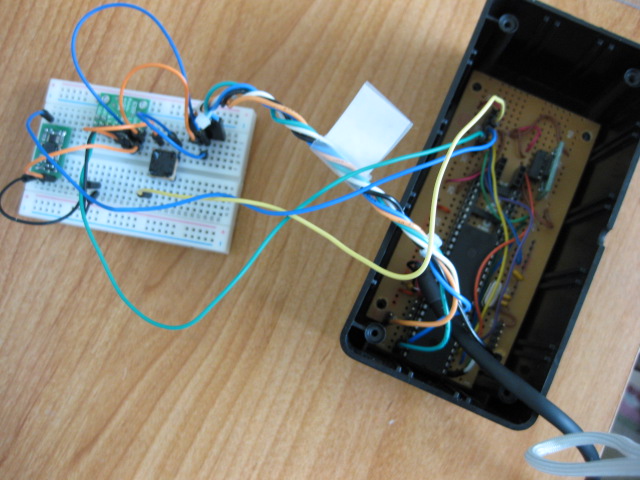
Recently I completed my Gamepad Configuration Utility and decided to put to use for something it was not necessarily built for. I connected 3 accelerometers (to precize their X axis output) to the analog ports of PIC18F4550 (one of my gamepad prototypes "The Brick").
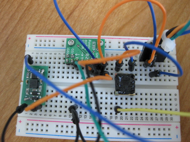
Here is a close-up, the devices are from left to right DE-ACCM2G (ADXL322), Pololu MMA7260QT and finally the reverse-mounted LIS244AL:
The chart below will give you a visual idea about the noise level these devices have:
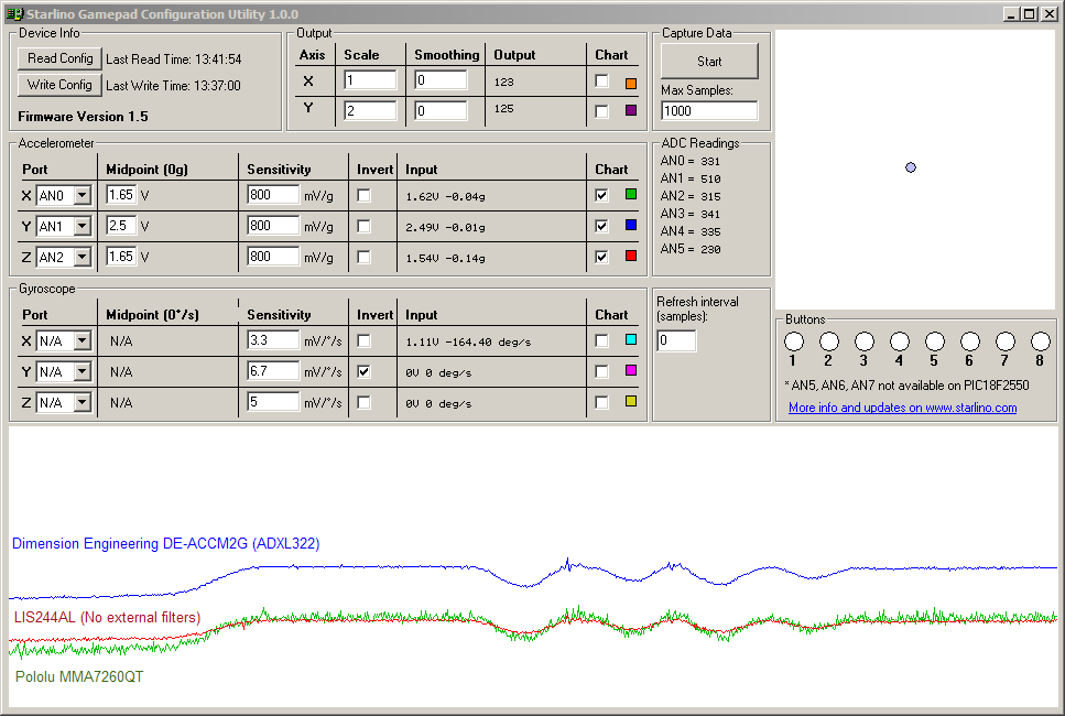
In the process of testing I tilted the device left and right. As you can see the ADXL322 and LIS244AL have very low noise levels, while MMA7260QT is very noisy. To be sure I tested with a second device I happen to have and the results where the same. The only way I could use the MMA7260QT in my gamepad was to place a 10uF !!! capacitor between it's output and ground, lower values were not effective enough . The Pololu breakout already has a 1K+0.1uF => 1/( 2PI * 1K * 0.1uF) ~ 1600Hz Low Pass filter, but apparently that's not enough. Of course the 10uF capacitor would decrease the threshold of this low pass filter, making the device less responsive, but still very much usable for this gamepad application.
Now if you compare the breakout DE-ACCM2G and the bare-bone LIS244AL you might be asking yourself why do I need a buffered device , when the simple device works just fine. Well it does, in this particular application , because our sample rate is not so fast (for USB reports we sample every 10ms or so) our PIC has plenty of sampling time. But if you would need to sample at faster rate the output impedance is an important factor. The buffer is basically an op-amp with negative feedback, often called "follower". It takes the high-impedance output from accelerometer and gives us it's own "low impedance" output. To put it in more plain words the ADC module cannot take so much current directly from accelerometer, but it can take current at a faster rate from the op-amp which reduces the required sampling time.
In conclusion I think the DE-ACCM2G is the best choice if you're concerned about noise and being able to sample at a fast rate. I am confident that the newer model DE-ACCM2G2 is also very good since it's base on LIS244AL which as you can see from the above chart has a low noise by itself.
//starlino//
Hello; I’m trying to get results from ADXL345 connected to MBED the problem is that what kind of treatement or formula I have to make to get 3 angles between the 3 axes?
I can read the contenent of internal registers and I get Rx, Ry and Rz.
#include “ADXL345.h”
ADXL345 accelerometer(p5, p6, p7, p8);
Serial pc(USBTX, USBRX);
int main() {
int readings[3] = {0, 0, 0};
pc.printf(“Starting ADXL345 test…\n”);
pc.printf(“Device ID is: 0x%02x\n”, accelerometer.getDevId());
//Go into standby mode to configure the device.
accelerometer.setPowerControl(0x00);
//Full resolution, +/-16g, 4mg/LSB.
accelerometer.setDataFormatControl(0x0B);
//3.2kHz data rate.
accelerometer.setDataRate(ADXL345_3200HZ);
//Measurement mode.
accelerometer.setPowerControl(0x08);
while (1) {
wait(0.1);
accelerometer.getOutput(readings);
//13-bit, sign extended values.
pc.printf(“%i, %i, %i\r\n”, (int16_t)readings[0], (int16_t)readings[1], (int16_t)readings[2]);
}
}