
In a previous article I have analized 3 accelerometer side by side comparing their noise level. Today I am going to test a 3 axis accelerometer from ST LIS331AL. I am going to compare it with the DE-ACCM2G accelerometer from Dimension Engeneering.
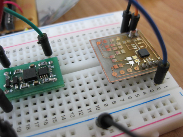
For testing purposes I have mounted the LIS331AL on a break-out board. If you're interested how this board can be done and device mounted make sure you read my article "DIY Surface Mount on a Budget".
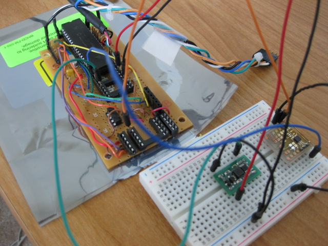
I have connected both accelerometers to my USB Gamepad device and will be using the Gamepad Configuration Software to trace the signals (although an osciloscope could be used instead).
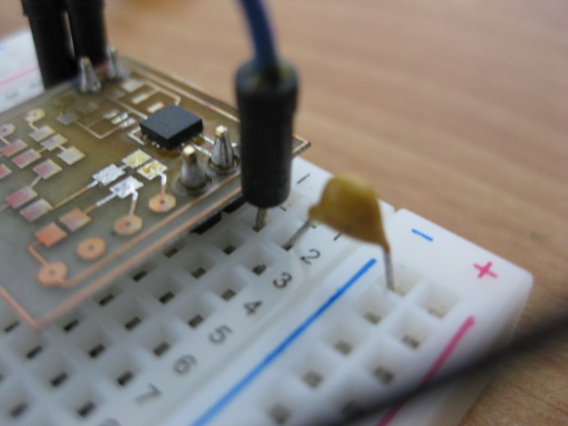
Here is a close-up of the accelerometers being tested:
 .
.
Please note that in the first phase of the test the LIS331AL will not have any filters so I can see it's intrinsic noise level.
Here are the test results:
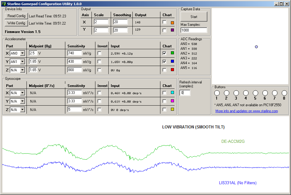
As you can see the noise level under low vibration , is acceptable compared to DE-ACCM2G.
To put the device further to the test I added some vibration , by touching the breadboard with an electric touthbrush and here are the output charts:
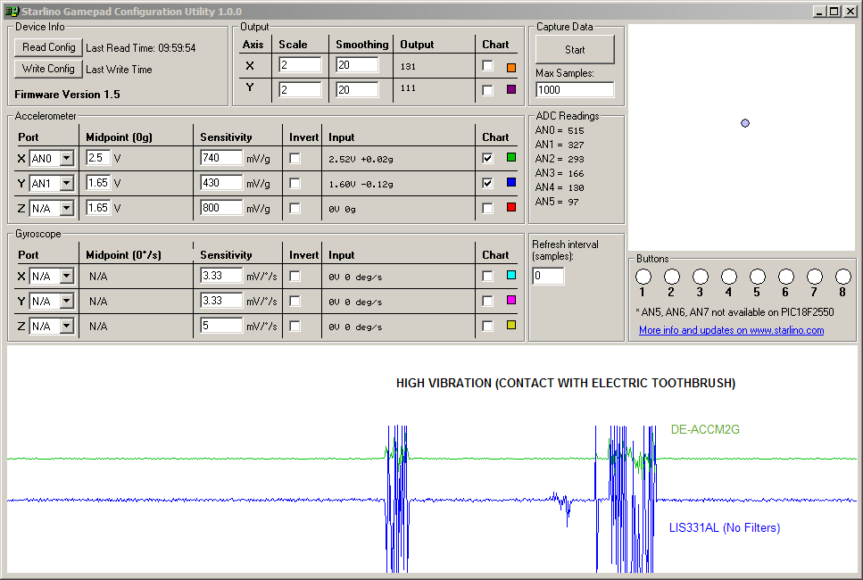
As you can see, without any filters LIS331AL has picked-up a big amount of vibration. This might be something you would want to remove or keep depending on your applicaiton. For example in applications where you would like to use the accelerometers to detect vibration (in cars, engines) a filter might be undesirable. For most applications however we'd like that noise smoothed out. If you look at LIS331AL datasheet you'll see that a 0.1uF capacitors will give us low-pass filter with a cut-off frequency of 50Hz.
So we're going to connect a 0.1uF capacitor between our output and gorund and repeat our tests.
This time I combined both tests (smooth tilt and high vibration) on the same chart:
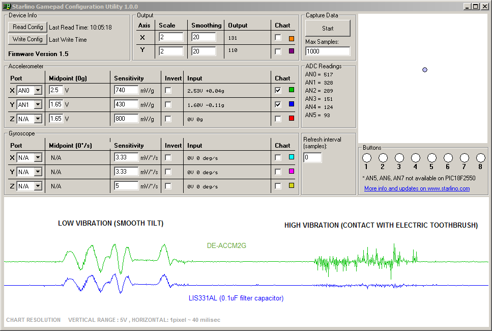
As you can see the filter capacitor makes a big difference. Because DE-ACCM2G has an amplifying circuit and different filter values the noise level was not reduced by so much.
In conclusion, when selecting an accelerometer board make sure you check that filter values are suitable for your application. Most boards that I saw , had a cut-off frequency of arround 50-100Hz. So they are targeted at a sample rate of arround 50-100 samples per second.
If you'd like to use the accelerometer to detect vibration you're better off without or with weaker filters (with higher cut-off frequency), on the other hand if you need to use the device to calculate angular data like inclination you might need filters that will eliminate more high-frequency signals (lower cut-off frequency).
//starlino//
Pingback: On-the-Go Slope Measurement - Page 6 - Fuel Economy, Hypermiling, EcoModding News and Forum - EcoModder.com